
Connector

A technology of connectors and connecting terminals, which is applied in the direction of connection, parts of connection devices, electrical components, etc., and can solve the problem that the flip cover cannot continue to press the FPC

Active Publication Date: 2017-08-18
BOE TECH GRP CO LTD +1
View PDF6 Cites 0 Cited by
  • Summary
  • Abstract
  • Description
  • Claims
  • Application Information

AI Technical Summary

Problems solved by technology

[0005] In order to solve the problem in the prior art that if the thickness of the FPC exceeds the predetermined thickness, the flip cover cannot continue to press the FPC, the embodiment of the present invention provides a connector

Method used


Image

  • Connector
  • Connector
  • Connector

Examples

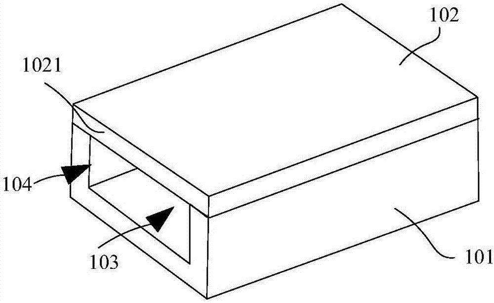
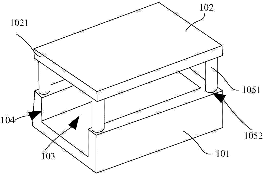
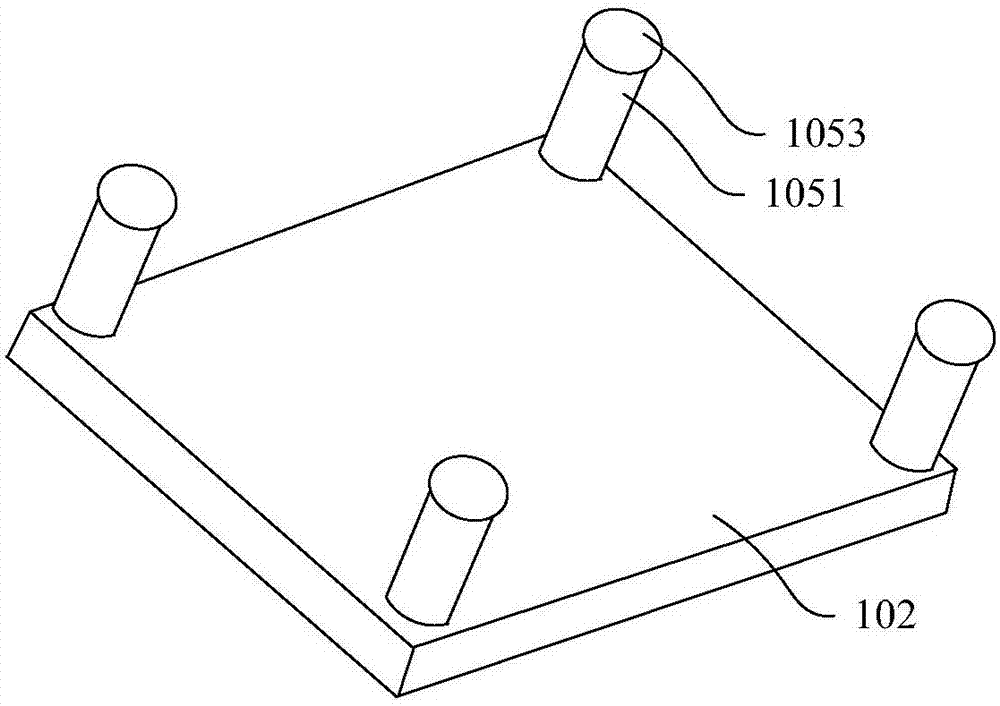

Embodiment Construction

[0025] In order to make the object, technical solution and advantages of the present invention clearer, the implementation manner of the present invention will be further described in detail below in conjunction with the accompanying drawings.

[0026] An embodiment of the present invention provides a connector, the connector includes: a base, connecting terminals and a cover plate, the cover plate is arranged on the top of the base, the base and the cover plate cooperate to form a cavity, the connecting terminals are arranged in the cavity, the base The side wall of the side wall is provided with an opening for the FPC terminal to extend into the cavity, the first side of the cover plate and the base are correspondingly provided with a limit structure, and the limit structure is used to limit the first side of the cover plate in the first position and the second position, the first side is the side of the cover above the opening, when the first side is in the first position, t...


PUM


Abstract

The invention discloses a connector, which belongs to the display field. The connector comprises a base, a connection terminal and a cover plate. The cover plate is arranged at the top part of the base. The base and the cover plate cooperate to form an empty cavity. The connection terminal is arranged in the empty cavity. The side wall of the base is provided with an opening used for a flexible circuit board's terminal to extend into the empty cavity. The first side edge of the cover plate and the base are provided with position limiting structures at corresponding positions. The position limiting structures are used to restrict the first side edge of the cover plate to move between the first position and the second position wherein the first side edge is the side edge of the cover plate located at the upper part of the opening. When the first side edge is located at the first position, the first side edge adheres to the base closely; and when the first side edge is located at the second position, a clearance is provided between the first side edge and the base; and in addition, the position limiting structures are used to provide suppression force when the first side edge moves from the first position to the second position.

Description

technical field [0001] The invention relates to the field of displays, in particular to a connector. Background technique [0002] In the field of liquid crystal display (English Liquid Crystal Display, referred to as LCD) module technology, the flexible circuit board (English Flexible Printed Circuit referred to as FPC) of the backlight module is mostly set on the printed circuit board (English Printed Circuit Board, referred to as PCB) The connector on the board (English Connector) is connected to the PCB board, and the PCB supplies power to the FPC. [0003] At present, the common connectors are mostly "piano cover" structure. The "piano cover" structure connector mainly includes the connector body, contact terminals and flip cover. The contact terminals are inserted on the connector body, and the flip cover can be rotatably connected to the connection on the device body. Specifically, one end of the flip cover plate is engaged with the rotation groove provided on the c...

Claims


Application Information

Patent Timeline
Patent Type & Authority Applications(China)
IPC IPC(8): H01R12/77H01R12/88H01R13/502
CPCH01R12/774H01R12/88H01R13/502H01R13/5025
Inventor 权雯琪闵航李玉成邵正坤
Owner BOE TECH GRP CO LTD
Learn More