Eureka AIR delivers breakthrough ideas for toughest innovation challenges, trusted by R&D personnel around the world.

Positioning tool for frame longitudinal beam

A technology for positioning tooling and longitudinal beams

Active Publication Date: 2021-11-23
DONGFENG LIUZHOU MOTOR
View PDF6 Cites 2 Cited by
  • Summary
  • Abstract
  • Description
  • Claims
  • Application Information

AI Technical Summary

Problems solved by technology

[0005] In order to solve the above problems, the object of the present invention is to provide a positioning tool for the longitudinal beam of the vehicle frame, so as to solve the problem that the existing movable chuck can only align the abdominal surface of the longitudinal beam Playing a pressing role, it is impossible to ensure that the lower wing surface of the longitudinal beam fits in place, the Z direction lacks the pressing force, once the force is applied, the positioning will be changed, and the positioning accuracy of the Z direction position is low; in addition, during the hoisting process, The guide precision between the pin groove and the pin shaft is low, and the effect on the longitudinal positioning of the longitudinal beam is poor

Method used


Image

  • Positioning tool for frame longitudinal beam
  • Positioning tool for frame longitudinal beam
  • Positioning tool for frame longitudinal beam

Examples


Embodiment Construction

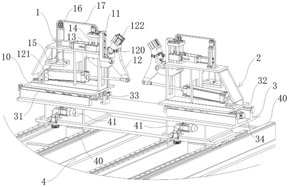
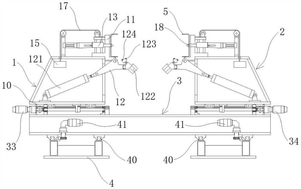
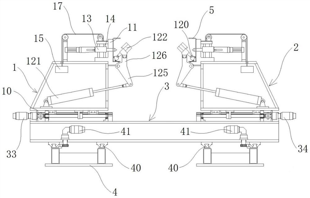
[0036] The specific implementation manners of the present invention will be further described in detail below in conjunction with the accompanying drawings and embodiments. The following examples are used to illustrate the present invention, but are not intended to limit the scope of the present invention.

[0037] Specific embodiment 1 of the positioning tool of the vehicle frame longitudinal beam of the present invention, as Figure 1 to Figure 3 As shown, the positioning tool for the frame longitudinal beam includes a base 3, a first mounting base 1 and a second mounting base 2 arranged at a distance from each other, and the first mounting base 1 and the second mounting base 2 are respectively moved and mounted on the base 3 , the moving direction of the first mounting seat 1 and the second mounting seat 2 are arranged along the width direction of the interval; the structure of the first mounting seat 1 and the second mounting seat 2 is the same, and the first mounting seat...


PUM


Abstract

The invention provides a positioning tool for a frame longitudinal beam, and relates to the field of frame assembly. The positioning tool comprises a base, a first mounting seat and a second mounting seat, the first mounting seat and the second mounting seat are oppositely arranged at an interval, the first mounting seat comprises a support, a fixing block, a pressing mechanism and a first driving part, and a positioning angle facing the interval position is arranged on the fixing block; the first driving part is connected with the pressing mechanism, and the pressing direction of a pressing head of the pressing mechanism obliquely extends towards the positioning angle so as to press the lower inner angle of the longitudinal beam; and a positioning sliding block is vertically installed on the support in a guiding manner, and a positioning pin of the positioning sliding block is used for being matched with an auxiliary hole in the longitudinal beam ventral face in a positioning manner. According to the tool, the longitudinal beam ventral face is positioned and pressed, the longitudinal beam lower wing face is positioned and pressed, the longitudinal beam is accurately positioned in the length direction, and the positioning accuracy in the Z direction and the length direction is improved; and for frames of different specifications and models, the positions of the first mounting seat and the second mounting seat in the interval width direction and the interval length direction can be adjusted, and automatic adaptation is achieved.

Description

technical field [0001] The invention relates to the technical field of frame assembly, in particular to a positioning tool for frame longitudinal beams. Background technique [0002] The truck frame assembly is usually assembled from components such as longitudinal beams, cross beams, and connecting plates. Among them, the longitudinal beam is the installation carrier for other components, and the positioning accuracy of the longitudinal beam is directly related to the assembly quality of the frame assembly. [0003] At present, the longitudinal beam positioning device is used to clamp and position the longitudinal beam. For example, the Chinese utility model patent with the authorized announcement number of CN201423426Y and the authorized announcement date of March 17, 2010 discloses a riveting assembly fixture for vehicle frame, and specifically discloses In addition to including the base, the base is provided with a plurality of tracks in the first direction of movement a...

Claims


Application Information

Patent Timeline
Patent Type & Authority Applications(China)
IPC IPC(8): B23K37/04
CPCB23K37/0443
Inventor 苏相三陈英昇周家明区锦文周礼民李岱圭陈家忠
Owner DONGFENG LIUZHOU MOTOR
Why Eureka
Eureka Blog
Learn More