Combined type wire wrapping equipment for mechanical equipment

A technology for mechanical equipment and winding equipment, applied in the field of combined winding equipment for mechanical equipment, can solve problems such as the inability to fundamentally prevent the winding device from sliding, the inability to simultaneously prevent the winding device from sliding left and right, and the disadvantage of winding efficiency. , to increase the scope of application, improve the anti-skid effect, and achieve the effect of high flexibility

Pending Publication Date: 2022-01-18
ZHEJIANG OCEAN UNIV
View PDF1 Cites 0 Cited by
  • Summary
  • Abstract
  • Description
  • Claims
  • Application Information

AI Technical Summary

Problems solved by technology

[0004] The purpose of the present invention is to provide a combined winding device for mechanical equipment. Through the design of the mounting plate, connecting components, support mechanism, winding mechanism, driving rod and driving component, the existing winding device for mechanical equipment is solved. It can only prevent the winding device from sliding in a certain direction, and cannot prevent the winding device from sliding left and right at the same time, so it cannot fundamentally prevent the sliding of the winding device. It is very troublesome to operate during winding, which is not conducive to improving the winding efficiency. and labor-intensive problems

Method used


Image

  • Combined type wire wrapping equipment for mechanical equipment
  • Combined type wire wrapping equipment for mechanical equipment
  • Combined type wire wrapping equipment for mechanical equipment

Examples


Embodiment 1

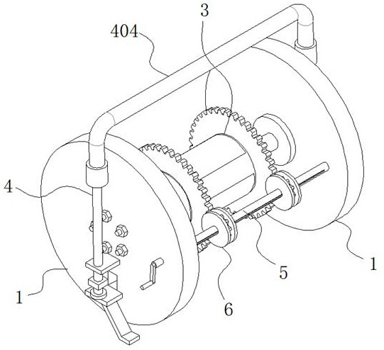
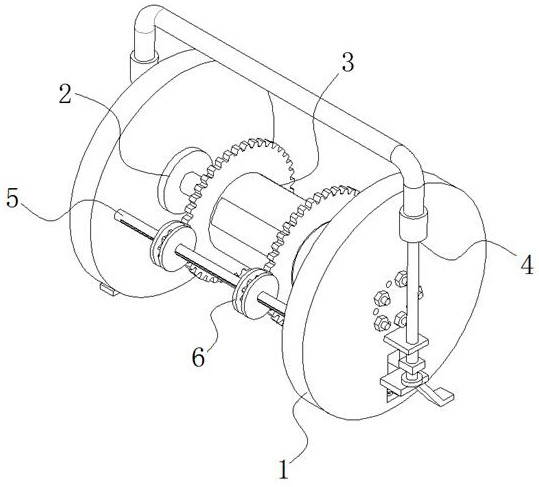
[0057] see Figure 1-16 , the present invention is a combined winding device for mechanical equipment, comprising two mounting discs 1 arranged oppositely;

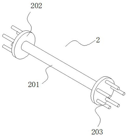
[0058] A support mechanism 2 is clamped between the two installation disks 1, which can be disassembled with the installation disk 1; the external thread of the support mechanism 2 is connected with a winding mechanism 3, and through the rotation of the winding mechanism 3, the mechanical equipment is connected with the cable Wrapped on the winding mechanism 3, the horizontal movement of the winding mechanism 3 on the support mechanism 2 can be realized by adopting the thread fit method;

[0059] A positioning plate 101 is fixedly connected to the side walls of the two mounting plates 1 away from the winding mechanism 3; the upper surface of the positioning plate 101 has a first through hole 102; the first through hole 102 is installed with a connecting component 4;

[0060] Wherein, the connecting assembly 4 includes a ...


PUM


Abstract

The invention discloses combined type wire wrapping equipment for mechanical equipment, and relates to the technical field of mechanical equipment. The equipment comprises two mounting discs which are oppositely arranged, a supporting mechanism is arranged between the two opposite mounting discs in a clamped mode, the exterior of the supporting mechanism is connected with a wire wrapping mechanism through threads, a first through hole is formed in the upper surface of a positioning plate, a connecting assembly is mounted in the first through hole, a connecting piece is fixedly connected to the upper end face of a connecting column, a clamping groove is formed in the top of the connecting piece, and a handle is connected to the interior of the clamping groove in a clamped mode. According to the equipment, through the design of a lifting handle, the connecting assembly, the first through hole, a first limiting groove channel, a reset spring and an anti-moving frame, a pressing plate downwards pushes and presses a moving plate by utilizing the gravity of a balancing weight, the moving plate downwards moves along the first limiting groove channel, and therefore the anti-moving frame is tightly attached to the ground; and the anti-moving frame can move upwards to the initial position by means of the reset spring, so that rolling of the two sides of the equipment is effectively prevented, and the problem of sliding during placement of the equipment is fundamentally solved.

Description

technical field [0001] The invention belongs to the technical field of mechanical equipment, in particular to a combined winding device for mechanical equipment. Background technique [0002] Equipment usually refers to the general term of production materials and material materials that can be used by people for a long time in production and basically maintain the original physical form and function in repeated use. Equipment includes general equipment and special equipment. General equipment includes mechanical equipment, electrical equipment, special equipment, office equipment, transportation vehicles, instruments and meters, computers and network equipment, etc. Special equipment includes mine special equipment, chemical special equipment, aerospace special equipment , Public security fire-fighting special equipment, etc. [0003] There are many existing winding devices for mechanical equipment on the market, among which the invention publication number is CN109052056B...

Claims


Application Information

Patent Timeline
IPC IPC(8): B65H75/44B65H75/40B65H75/24
CPCB65H75/4492B65H75/406B65H75/4457B65H75/241B65H2701/32B65H2701/34B65H2701/35
Inventor 罗欣宇王旭明
Owner ZHEJIANG OCEAN UNIV
Why Eureka
Try Eureka