padlock

A padlock and lock beam technology, applied in the field of smart locks, can solve problems such as unstable locking of padlocks

Active Publication Date: 2021-08-20
ZHUHAI UNITECH POWER TECH CO LTD
View PDF7 Cites 0 Cited by
  • Summary
  • Abstract
  • Description
  • Claims
  • Application Information

AI Technical Summary

Problems solved by technology

[0005] The main purpose of the present invention is to provide a padlock to solve the problem of unstable locking of padlocks in the prior art

Method used


Image

  • padlock
  • padlock
  • padlock

Examples


Embodiment Construction

[0033] It should be noted that, in the case of no conflict, the embodiments in the present application and the features in the embodiments can be combined with each other. The present invention will be described in detail below with reference to the accompanying drawings and examples.

[0034] It should be noted that, unless otherwise specified, all technical and scientific terms used in this application have the same meaning as commonly understood by those of ordinary skill in the art to which this application belongs.

[0035] In the present invention, unless stated otherwise, the used orientation words such as "upper, lower, top, bottom" are usually for the directions shown in the drawings, or for the parts themselves in the vertical, In terms of vertical or gravitational direction; similarly, for the convenience of understanding and description, "inner and outer" refer to the inner and outer relative to the outline of each component itself, but the above orientation words ...


PUM


Abstract

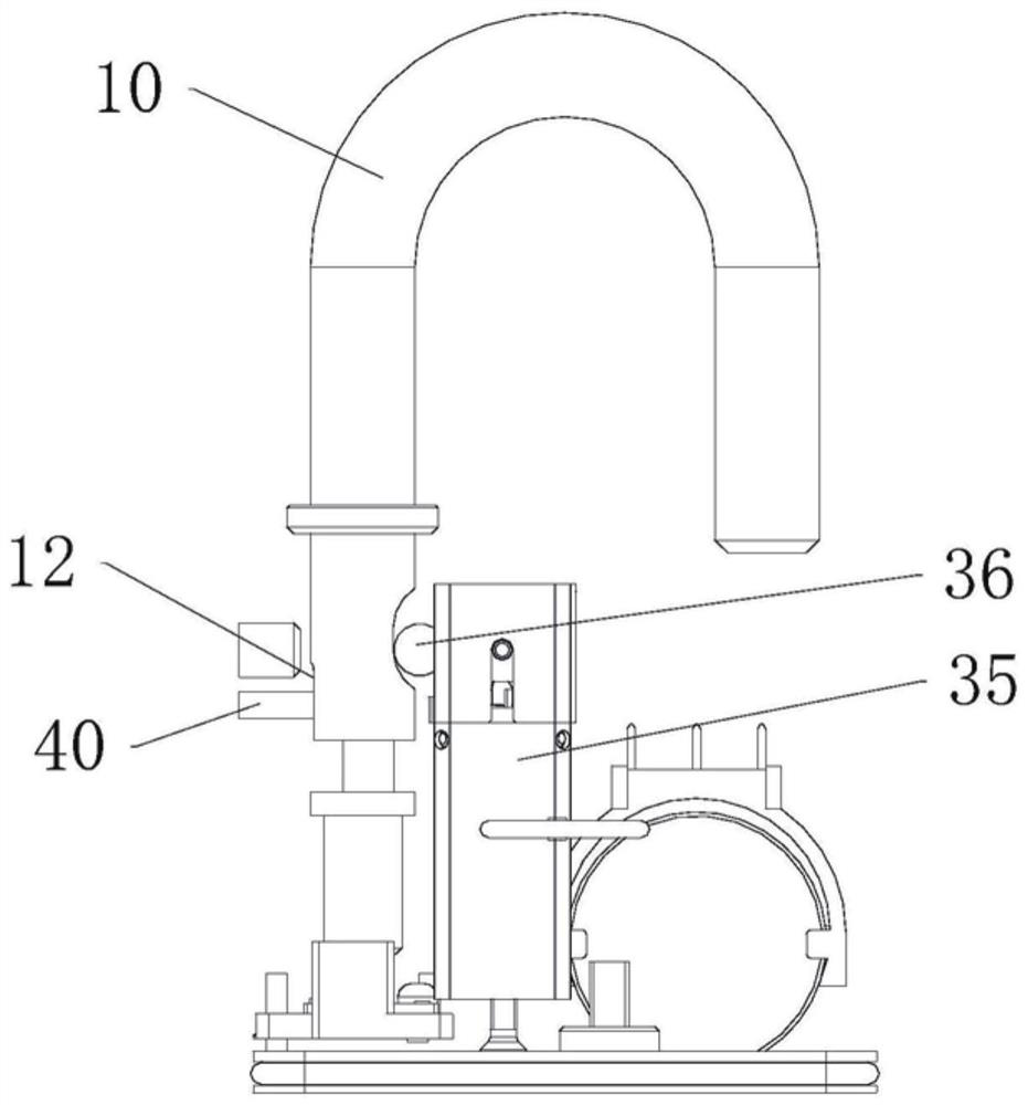
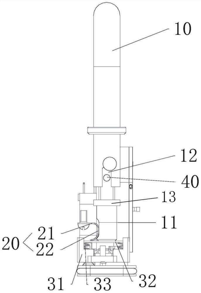
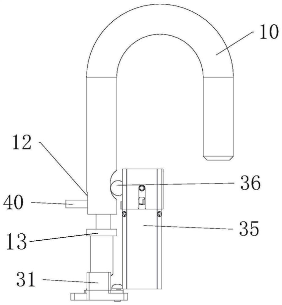
The invention provides a padlock. The padlock includes: a lock case; a lock beam, the locking end of which is located in the lock case, and the lock beam can slide relative to the lock case at least along a first direction; an extrusion, at least a part of which is arranged in the lock case, The extrusion part can provide the lock beam with an extrusion force in at least the second direction, and the first direction is perpendicular to the second direction; the locking component is arranged in the lock housing, and the ball of the locking component is locked or unlocked with the lock beam , the extrusion keeps the lock beam locked to the locking assembly. The invention solves the problem of unstable locking of the padlock in the prior art.

Description

technical field [0001] The invention relates to the field of intelligent locks, in particular to a padlock. Background technique [0002] At present, padlocks with bluetooth functions are constantly emerging. The bluetooth padlocks on the market can be roughly divided into two types: bolt lock and ball lock. The locking of the lock bolt means that the motor drives the locking mechanism, so that the lock bolt (generally columnar or approximately columnar) moves from the unlocked position to the locked position, thereby realizing the locking of the padlock. The ball lock is that the motor drives the locking mechanism, so that the ball moves from the unlocked position to the locked position, thereby realizing the locking of the padlock. [0003] When the ball locking method is adopted, since there are gaps between the lock beam and the lock housing, and between the lock beam and the balls, there is relative sliding between the lock beam and the balls, thereby affecting the per...

Claims


Application Information

Patent Timeline
Patent Type & Authority Patents(China)
IPC IPC(8): E05B67/22
Inventor 李保福李启平杨绍华高静远
Owner ZHUHAI UNITECH POWER TECH CO LTD
Why Eureka
Try Eureka