Eureka AIR delivers breakthrough ideas for toughest innovation challenges, trusted by R&D personnel around the world.

Support structure for hybrid SSD

A technology of support mechanism and support plate, applied in the field of SSD, can solve the problems of inability to adjust the space size of the mixed SSD, the heat dissipation performance of the mixed SSD is deteriorated, and the service life of the hard disk is affected, so as to achieve a simple structure, improve the scope of application, and improve the disassembly and assembly efficiency Effect

Active Publication Date: 2021-08-10
QUZHOU UNIV
View PDF7 Cites 0 Cited by
  • Summary
  • Abstract
  • Description
  • Claims
  • Application Information

AI Technical Summary

Problems solved by technology

[0005] The purpose of the present invention is to provide a supporting structure for a hybrid SSD, through a U-shaped clamping plate, a first through hole, a third limiting channel, a two-way threaded rod, a supporting mechanism, a tooth structure, an SSD positioning component and a fixing component The design solves the problem that the existing supporting structure for SSD is not easy to install and disassemble, and most of the structures are fixed, so the space size of the installation part of the hybrid SSD cannot be adjusted, which has great limitations. In addition, the hybrid SSD When installed on the support structure, the hybrid SSD is mostly in close contact with the support structure, which makes the heat dissipation performance of the hybrid SSD worse, which in turn affects the service life of the hard disk.

Method used


Image

  • Support structure for hybrid SSD
  • Support structure for hybrid SSD
  • Support structure for hybrid SSD

Examples


Embodiment Construction

[0040] The following will clearly and completely describe the technical solutions in the embodiments of the present invention with reference to the accompanying drawings in the embodiments of the present invention. Obviously, the described embodiments are only some, not all, embodiments of the present invention. Based on the embodiments of the present invention, all other embodiments obtained by persons of ordinary skill in the art without creative efforts fall within the protection scope of the present invention.

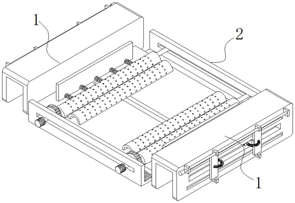
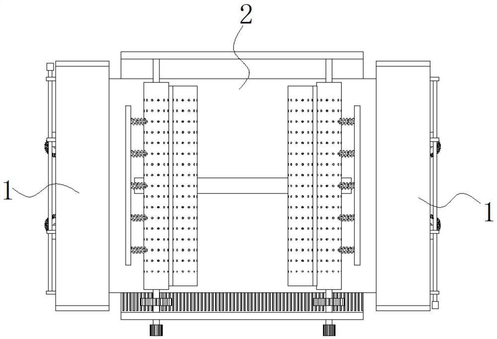
[0041] see Figure 1-10 , the present invention is a supporting structure for a hybrid SSD, comprising two symmetrically arranged fixing mechanisms 1;

[0042] A supporting mechanism 2 is fixedly connected between the two fixing mechanisms 1 for supporting and fixing the hybrid SSD;

[0043] Wherein, the support mechanism 2 includes a support plate 201; an L-shaped plate 202 is fixed on opposite sides of the support plate 201;

[0044]Two SSD positioning componen...


PUM


Abstract

The invention discloses a supporting structure for a hybrid SSD, and relates to the technical field of SSDs. The device comprises two fixing mechanisms which are symmetrically arranged; wherein a supporting mechanism is fixedly connected between the two fixing mechanisms; L-shaped plates are fixed on two opposite side surfaces of the supporting plate; two SSD positioning assemblies are arranged between the two oppositely-arranged L-shaped plates in a sliding fit mode. The fixing mechanism comprises a U-shaped clamping plate; wherein the U-shaped clamping plate is fixedly connected with the supporting plate; a first through hole is formed in one surface of the U-shaped clamping plate; two fixing assemblies are arranged in the first through hole. A first limiting groove channel, a second limiting groove channel, a second through hole, a tooth-shaped structure, an SSD positioning assembly, a supporting rod, a rotating shaft and a driving fluted disc are designed; so that when the rotating shaft is rotated, the SSD positioning assemblies are driven to move horizontally through the meshing effect of the driving fluted disc and the tooth-shaped structure, and the horizontal distance between the two SSD positioning assemblies is flexibly adjusted. Therefore, the hybrid SSDs of different sizes are fixed, and the application range of the method is greatly widened.

Description

technical field [0001] The invention belongs to the technical field of SSDs, in particular to a supporting structure for hybrid SSDs. Background technique [0002] In the past half a century, with the continuous progress of computer architecture technology and chip processing technology, the gap between CPU performance and input-output (IO) performance of computer systems has continued to widen. The bottleneck of the IO performance of the computer system lies in the hard disk (Hard Disk Drive, HDD). Although the HDD capacity has been greatly improved in recent years, the access speed is limited due to the mechanical rotation structure. For example, in the past 20 years, the CPU frequency has increased by about 600 times, while the hard disk speed has only increased by more than 20 times. Compared with disks, flash memory (Flash Memory) is a chip-level storage medium with high speed, low power consumption, shock resistance, compactness and lightness. It is considered to be ...

Claims


Application Information

Patent Timeline
Patent Type & Authority Applications(China)
IPC IPC(8): G06F1/18G06F1/20
CPCG06F1/187G06F1/20
Inventor 顾能华吕梅蕾陈勇叶文通朱秋琴徐拥华
Owner QUZHOU UNIV
Why Eureka
Eureka Blog
Learn More