

Delay illumination switch
A technology for lighting switches and lighting lamps, which is applied to lighting devices, light sources, electrical components, etc., can solve problems such as the charging of lamp sockets of lighting bulbs, and achieve the effect of saving energy consumption.
- Summary
- Abstract
- Description
- Claims
- Application Information
AI Technical Summary
Problems solved by technology
Method used
Image

Examples
Embodiment 1
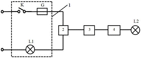
[0024] The invention provides a time-delay lighting switch, such as figure 1 As shown, it includes a normal lighting switch circuit 1, a voltage divider circuit 2, a power storage unit 3, an auxiliary lamp driving circuit 4 and an auxiliary lamp L2, wherein the normal lighting switch circuit is used to control the normal lighting or extinguishing of the lighting lamp L1 , consisting of a lighting switch K, a fuse G, and a lighting lamp L1 connected in series at both ends of the AC power supply in sequence; During lighting, that is, when the switch K is turned on, part of the voltage is taken and charged to the power storage unit 3. One end of the auxiliary lamp drive circuit 4 is connected to the output end of the power storage unit 3, and the other end is connected to the auxiliary lamp L2 for controlling the power storage unit. The electric unit 3 supplies power to the auxiliary lamp after the illuminating lamp is extinguished to delay lighting or extinguishing.
[0025] Su...
Embodiment 2
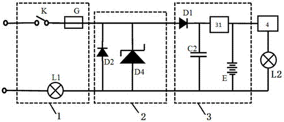
[0030] Such as Figure 4 As shown, the present embodiment is basically the same as Embodiment 1, and its difference only lies in:
[0031] The power storage unit 3 is composed of a diode D1, a battery charging circuit 31, a rechargeable battery E and a filter capacitor C2. Among them, the diode D1 is used to control the unidirectional flow of current, the battery charging circuit 31 is used to control the voltage divider circuit 2 to charge the rechargeable battery E, and the filter capacitor C2 is used to stabilize the voltage across the rechargeable battery E and prevent its fluctuation. In practical applications, when the voltage across the rechargeable battery E is not strictly required, the filter capacitor C2 can also be omitted as needed.
[0032] The voltage divider circuit 2 is formed by a zener diode D4 connected in parallel with a reversely connected diode D2, wherein the zener diode D4 is used to stabilize the voltage at the input end of the power storage unit 3, ...
Embodiment 3
[0036] Such as Figure 7As shown, the difference between this embodiment and Embodiment 2 is only that: the voltage divider circuit 2 includes a diode D2, a Zener diode D5, current limiting resistors R1, R2 and a transistor Q. Among them, the transistor Q is used to stabilize the voltage at the input terminal of the power storage unit 3, the voltage regulator diode D5 is used to provide the reference voltage for the transistor Q, the diode D2 is used to bypass the reverse current in the voltage dividing circuit 2, the current limiting resistor R1, R2 and transistor Q make the current that can pass in the normal lighting circuit larger, which is suitable for the lighting lamp L1 of higher power.
PUM
 Abstract
Description
Claims
Application Information