
Full-automatic motor rotor cleaning machine

A technology for motor rotors and cleaning machines, which is applied to cleaning methods and utensils, cleaning methods using tools, chemical instruments and methods, etc., can solve problems such as low efficiency, inconvenient rotation, and poor effects.

Inactive Publication Date: 2017-08-22
DONGGUAN LIANZHOU INTPROP OPERATION MANAGEMENT CO LTD
View PDF0 Cites 9 Cited by
  • Summary
  • Abstract
  • Description
  • Claims
  • Application Information

AI Technical Summary

Problems solved by technology

[0004] Existing motor rotors generally need to be cleaned before testing, and the dust on the outer surface is wiped. The existing method is generally manual wiping. It needs to turn the motor rotor upright, and then rotate the motor rotor while Wiping, its efficiency is low, the effect is not good, the motor rotor is heavy, when it is vertical, it needs a lot of manual force to support it, it is very tiring, and it is very inconvenient to rotate

Method used


Image

  • Full-automatic motor rotor cleaning machine
  • Full-automatic motor rotor cleaning machine

Examples


Embodiment Construction

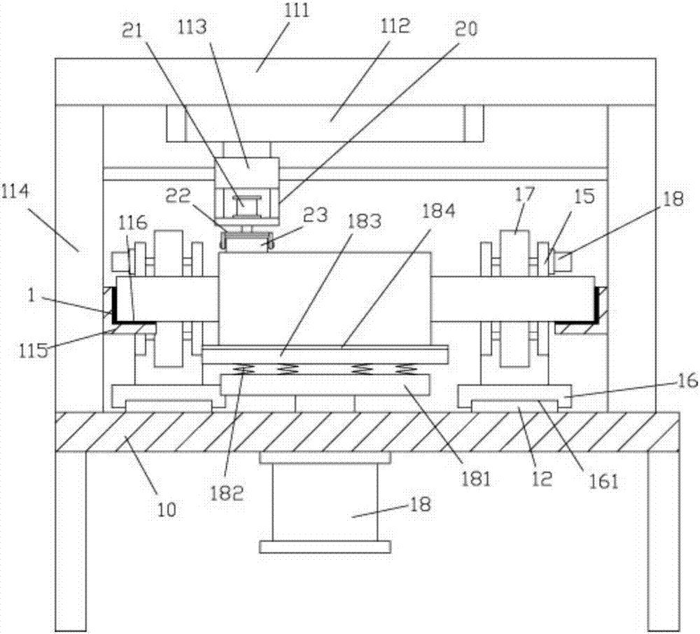
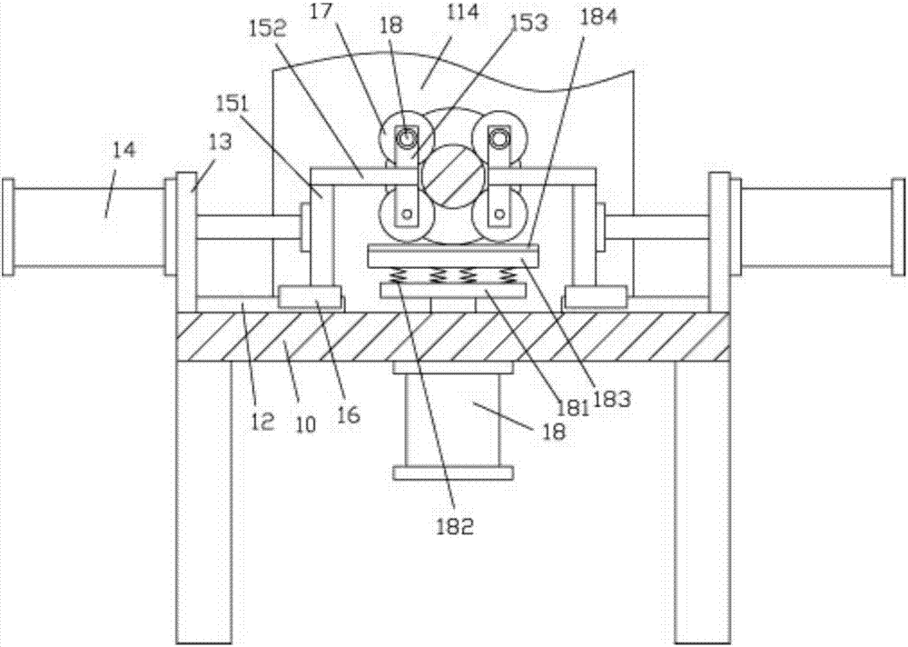
[0021] Examples, see e.g. Figure 1 to Figure 2 As shown, a fully automatic motor rotor cleaning machine includes a frame 10, the top surfaces of both sides of the top plate of the frame 10 are fixed with main side support plates 114, and the tops of the two main side support plates 114 are fixed on the top for cleaning On the bottom surface of the support plate 111, a rodless cylinder 112 is fixed on the middle part of the bottom surface of the upper cleaning support plate 111, and the push block of the rodless cylinder 112 is vertically downward and is fixed with an upper moving block 113, and the bottom surface of the upper moving block 113 is fixed with a support Frame 20, the top surface of the bottom plate of support frame 20 is fixed with telescopic cylinder 21, and the push rod of telescopic cylinder 21 passes the bottom plate of support frame 20 and is fixed with roller cleaning frame 22, is hinged with cleaning plush roller body in the roller cleaning frame 22 twenty...


PUM


Abstract

The invention discloses a full-automatic motor rotor cleaning machine. The full-automatic motor rotor cleaning machine comprises a rack, main side supporting plates are fixed on the top surfaces of the two sides of a top plate of the rack, and the top ends of the two main side supporting plates are fixed on the undersurface of an upper cleaning supporting plate; a rod-less cylinder is fixed at the middle part of the undersurface of the upper cleaning supporting plate, an upper moving block is fixed on a vertically downward pushing block of the rod-less cylinder, a support frame is fixed on the undersurface of the upper moving block, a telescopic cylinder is fix on the top surface of a base plate of the support frame, a roller cleaning frame is fixed on a push rod, passing through the base plate of the support frame, of the telescopic cylinder, and a cleaning plush roller body is hinged in the roller cleaning frame; and a placing block is fixed on the inside wall of each main side supporting plate, a placing groove is formed in the top surface of each placing block, one ends of the placing grooves extend out of corresponding end faces of the two placing blocks, and guiding strips are fixed on the top surfaces of the front and the back portions of the left and the right ends of the top plate of the rack. With the full-automatic motor rotor cleaning machine, the two ends of a motor rotor are placed on the placing blocks, rotating and cleaning are automatic, and cleaning is quite convenient.

Description

[0001] Technical field: [0002] The invention relates to the technical field of motor processing and detection, and more specifically relates to a fully automatic motor rotor cleaning machine. [0003] Background technique: [0004] Existing motor rotors generally need to be cleaned before testing, and the dust on the outer surface is wiped. The existing method is generally manual wiping. It needs to turn the motor rotor upright, and then rotate the motor rotor while Wiping, its efficiency is low, the effect is not good, the rotor of the motor is heavy, and when it is vertical, it needs a lot of manual power to support it, which is very tiring, and it is very inconvenient to rotate. [0005] Invention content: [0006] The purpose of the present invention is to overcome the deficiencies of the prior art and provide a fully automatic motor rotor cleaning machine, which can place both ends of the motor rotor on the placement block and automatically rotate and clean automaticall...

Claims


Application Information

Patent Timeline
IPC IPC(8): B08B1/02B08B13/00
CPCB08B13/00B08B1/143B08B1/20
Inventor 徐亚维
Owner DONGGUAN LIANZHOU INTPROP OPERATION MANAGEMENT CO LTD
Learn More