
Elevator traction machine

An elevator traction machine and traction machine technology, applied in the field of elevators, can solve problems such as unbalanced force, achieve the effects of large car unbalanced load, flexible layout, and reduced design and selection requirements

Pending Publication Date: 2017-08-22
SJEC CORP
View PDF6 Cites 1 Cited by
  • Summary
  • Abstract
  • Description
  • Claims
  • Application Information

AI Technical Summary

Problems solved by technology

[0004] For example, Chinese Patent No. 201420039508.8, a utility model patent named "Traction Machine with Double Traction Wheels", discloses a traction machine with two traction wheels spaced apart on the main shaft of the traction machine. The two traction wheels are different from the conventional traction wheel arrangement, but the two traction wheels are located on the same side of the drive mechanism, so there is still the problem of unbalanced force

Method used


Image

  • Elevator traction machine
  • Elevator traction machine

Examples


Embodiment Construction

[0019] Preferred embodiments of the present invention will be described in detail below in conjunction with the accompanying drawings.

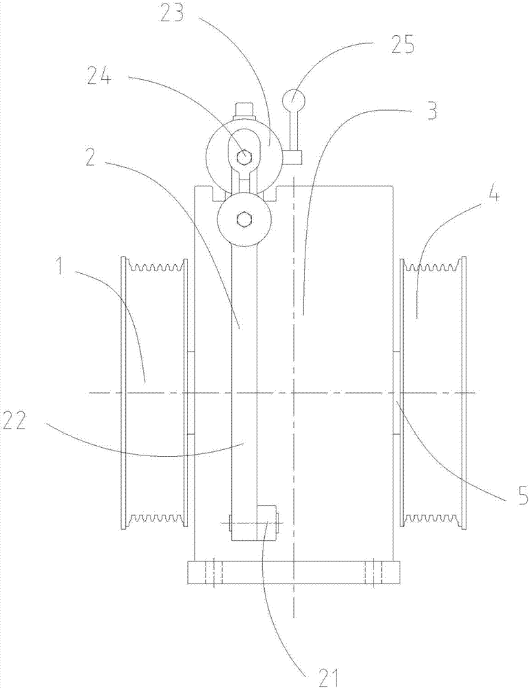
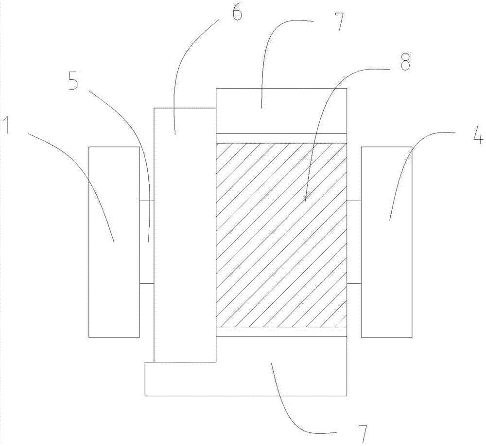
[0020] Such as Figure 1-2 As shown, an elevator traction machine of the present invention includes a traction sheave, a traction machine cylinder 3, and a braking device installed on the traction machine cylinder 3 for stopping the rotation of the traction sheave. The engine cylinder body 3 is provided with a driving device that drives the rotation of the traction sheave. The traction sheave includes a left traction sheave 1 and a right traction sheave 4 arranged on both sides of the driving device. The driving device is provided with a rotating shaft 5, and the left traction sheave The wheel 1 and the right traction sheave 4 are respectively located at the two ends of the rotating shaft 5 .

[0021] The driving device includes a traction machine stator assembly 7 and a traction machine rotor assembly 8 arranged in the traction machine stat...


PUM


Abstract

The invention discloses an elevator traction machine. The elevator traction machine comprises traction wheels, a traction machine cylinder body and a braking device which is mounted on the traction machine cylinder body and used for stopping the rotation of the traction machine, wherein a driving device for driving the traction wheels to rotate is arranged in the traction machine cylinder body; the traction wheels comprise a left traction wheel arranged on the left side of the driving device and a right drawing wheel arranged on the right side of the driving device; the traction device is provided with a rotating shaft; and the left traction wheel and the right traction wheel are respectively located at two end parts of the rotating shaft. According to the elevator traction machine disclosed by the invention, two traction wheels are symmetrically arranged on two sides of the traction machine cylinder body; the structure is adopted, so that requirements for bearing design and type selection of the traction machine rotating shaft can be reduced; the load is uniformly distributed, and balance of the integral stress of the traction machine is facilitated; for the complete elevator, the gravity center of a lift car is located at the center position of two sets of hanging rope systems, so that a good stressed state of the lift car can be obtained; the arrangement is flexible, and greater lift car eccentric load can be borne.

Description

technical field [0001] The invention relates to the technical field of elevators, in particular to an elevator traction machine. Background technique [0002] With the rapid development of social economy and the continuous improvement of people's living standards, elevators have become an indispensable part of daily life. [0003] When installing the elevator, the main beam will be installed above the elevator shaft, and the traction machine will be installed above the main beam. Most of the traction machines in the prior art adopt a cantilever mounting structure: including a machine base, a main shaft is provided as a rotational support in the machine base, and the main shaft is driven by a motor fixed at one end of the machine base, and a traction wheel is installed at one end of the main shaft. The rotation of the motor can drive the traction sheave to rotate through the main shaft. Therefore, the structure of the traditional traction machine is stressed at one end, the...

Claims


Application Information

Patent Timeline
Patent Type & Authority Applications(China)
IPC IPC(8): B66B11/04
CPCB66B11/04
Inventor 钱松陶宪德
Owner SJEC CORP
Features
  • Generate Ideas
  • Intellectual Property
  • Life Sciences
  • Materials
  • Tech Scout
  • Unparalleled Data Quality
  • Higher Quality Content
  • 60% Fewer Hallucinations
Learn More