Rotary multipath fuse

A fuse and rotary technology, applied in the field of power facilities, can solve problems such as long overload response time and difficulty in meeting safety requirements, and achieve the effect of ensuring safety

Inactive Publication Date: 2017-08-22
佛山市广明熔断器有限公司
View PDF4 Cites 26 Cited by
  • Summary
  • Abstract
  • Description
  • Claims
  • Application Information

AI Technical Summary

Problems solved by technology

[0002] In the field of power protection facilities, commonly used protection units include thermal relays and fuses; for thermal relays, they are automatically disconnected when the circuit is overloaded, and can be automatically closed after cooling; the disadvantage is that the overload response time is long, and it needs to wait until its The circuit can only be disconnected after the bimetal sheet is deformed, which is difficult to meet the high safety requirements; and for the current fuse, after the fuse is overloaded and blown, the circuit needs to be replaced manually to restore the circuit, which will give ordinary Residents cause more trouble

Method used


Image

  • Rotary multipath fuse
  • Rotary multipath fuse
  • Rotary multipath fuse

Examples


Embodiment 1

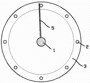
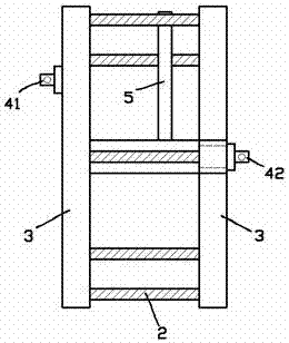
[0013] exist figure 1 , figure 2 In the first embodiment shown, the rotary multi-way fuse includes a clockwork shaft 1 that can rotate slowly as the mainspring is released. The main shaft of the clock and watch is formed, and will not be described in detail; with the clockwork shaft 1 as the central axis, there are 8 fuses 2 evenly distributed in the circumferential direction; the two ends of each fuse 2 are fixed by a circular bracket 3; and each fuse 2. The ends on one of the circular brackets 3 are commonly electrically connected to the first terminal 41; the clockwork shaft 1 is provided with a radially extending conductive rod 5, and the conductive rod 5 is unconstrained In the state, it can follow the clockwork shaft 1 to rotate; the conductive rod 5 is blocked by the fuse 2 and is pressed on a fuse under the elastic force of the clockwork shaft 1; the conductive rod 5 is electrically Connect to the second terminal 42 on the circular support 3 .

[0014] The above-me...

Embodiment 2

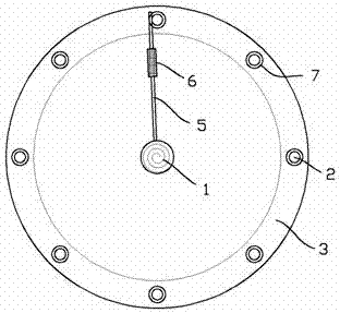
[0016] exist image 3 , Figure 4 In the shown second embodiment, different from the first embodiment, an electromagnet 6 is penetrated near the free end of the conductive rod 5, and each fuse 2 is sleeved with a short section that is not connected with the conductive rod 5. The iron pipe 7 in contact; thus, when a fuse 2 is blown, the free end of the conductive rod 5 gradually rotates before the next fuse, such as an arc occurs between the fuse 2 and the conductive rod 5 (on the conductive rod 5 slowly approaching the fuse 2, the possibility of arcing is greater), then the electromagnet 6 is switched on, and forms a magnetic attraction force with the iron pipe 7, so that the conductive rod 5 is quickly pressed against the fuse, so that the The arc is extinguished. Further, the conductive rod 5 is in the shape of a sheet, and the plane of the sheet is parallel to the fuse 2, so as to push a significant airflow to the fuse 2 in the process of rapidly approaching the fuse, so ...


PUM


Abstract

The invention provides a rotary multipath fuse comprising a spring shaft which is slowly rotatable with the loosening of a spring. More than two fuse wires are uniformly arranged circumferentially by using the spring shaft as a central axis. Both ends of each fuse wire are fixed by circular supports. The end portions, on one of the circular supports, of the fuse wires are electrically connected to a first wiring terminal. The spring shaft is provided with a conductive rod extending in the radial direction. The conductive rod is rotatable with the spring shaft in an unconstrained state, is stopped by the fuse wires so as to be pressed against one of the fuse wires under the effect of the resilient force of the spring shaft; and is electrically connected to a second wiring terminal on the circular supports. The fuse can be quickly fused when a circuit is overloaded and can automatically recover the circuit after a delayed time period.

Description

technical field [0001] The invention relates to the field of power facilities, in particular to a fuse. Background technique [0002] In the field of power protection facilities, commonly used protection units include thermal relays and fuses; for thermal relays, they are automatically disconnected when the circuit is overloaded, and can be automatically closed after cooling; the disadvantage is that the overload response time is long, and it needs to wait until its The circuit can only be disconnected after the bimetal sheet is deformed, which is difficult to meet the high safety requirements; and for the current fuse, after the fuse is overloaded and blown, the circuit needs to be replaced manually to restore the circuit, which will give ordinary Residents cause a lot of trouble. Contents of the invention [0003] In view of the above problems, the object of the present invention is to provide a rotary multi-circuit fuse, which can be quickly blown when the circuit ...

Claims


Application Information

Patent Timeline
Patent Type & Authority Applications(China)
IPC IPC(8): H01H85/055H01H85/28
CPCH01H85/055H01H85/28H01H2085/0555
Inventor 马人欢
Owner 佛山市广明熔断器有限公司
Why Eureka
Try Eureka