Charging pile and charging system

A charging pile and charging electrode technology, which is applied in the field of automatic charging devices, can solve problems such as angle deviation, poor contact between charging electrodes and receiving electrodes, etc.

Active Publication Date: 2017-08-22
SMART DYNAMICS CO LTD
View PDF6 Cites 11 Cited by
  • Summary
  • Abstract
  • Description
  • Claims
  • Application Information

AI Technical Summary

Problems solved by technology

[0004] In view of this, the embodiment of the present invention provides a charging pile and a charging system, which solves the problem of poor contact between the charging electrode and the receiving electrode due to the angular deviation between the specific posture of the automatic charging robot at the docking position and the specified posture.

Method used


Image

  • Charging pile and charging system
  • Charging pile and charging system
  • Charging pile and charging system

Examples


Embodiment Construction

[0015] The following will clearly and completely describe the technical solutions in the embodiments of the present invention with reference to the accompanying drawings in the embodiments of the present invention. Obviously, the described embodiments are only some of the embodiments of the present invention, not all of them. Based on the embodiments of the present invention, all other embodiments obtained by persons of ordinary skill in the art without creative efforts fall within the protection scope of the present invention.

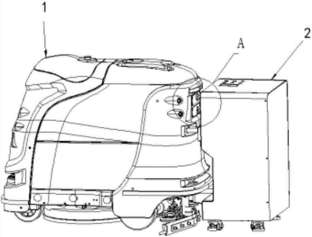
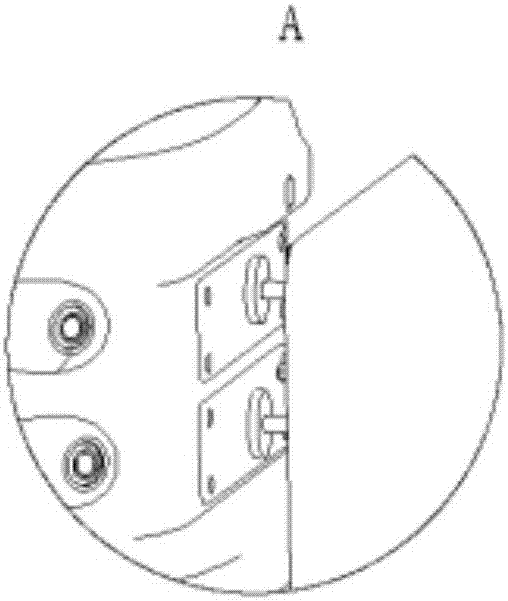
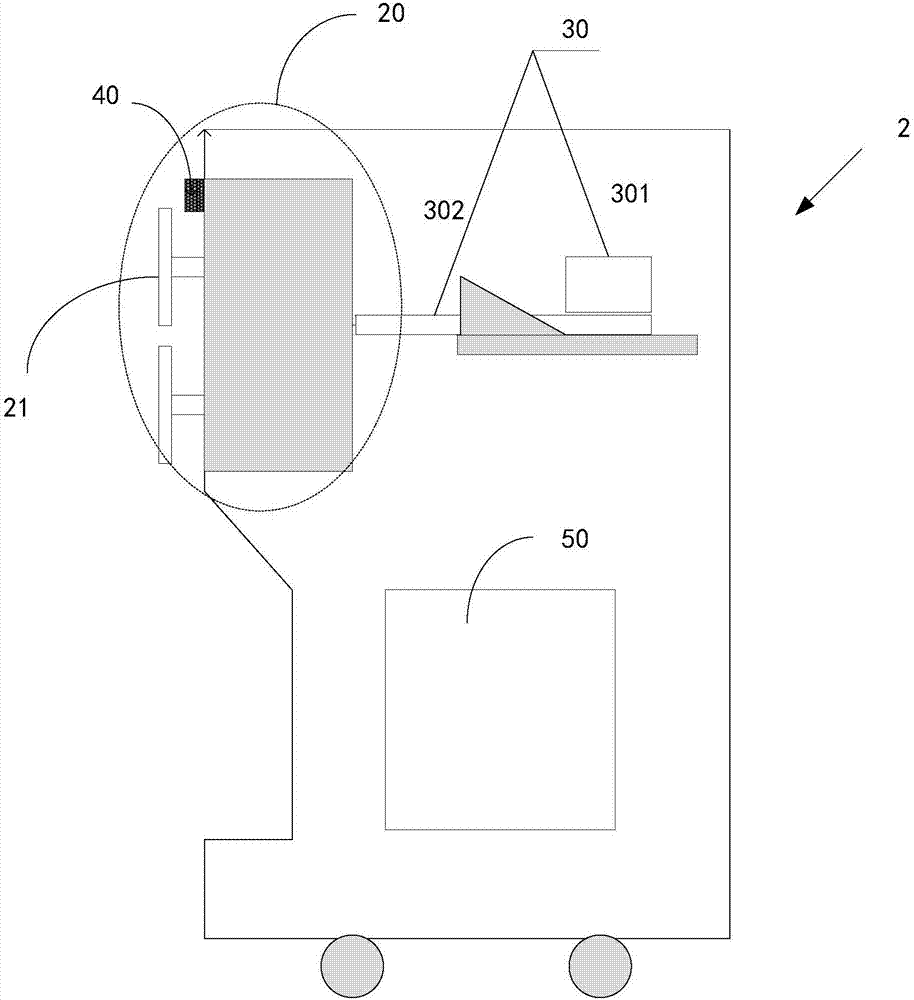
[0016] image 3 Shown is a schematic diagram of the side structure of the charging pile 2 provided by an embodiment of the present invention. Figure 4 for image 3 The schematic diagram of the three-dimensional structure of area B in the charging pile shown. From image 3 It can be seen from the figure that the charging pile 2 includes a charging unit 20, a telescoping unit 30, a ranging unit 40 and a processor 50, wherein the ranging unit 40, the...


PUM


Abstract

The embodiment of the invention provides a charging pile and a charging system, so that a problem that poor contact between a charging electrode and an electrified electrode is caused by an angle offset between the concrete attitude and a specified attitude of an automatic charging robot at a stopping place can be solved. The charging pile comprises a charging unit, a range finding unit, a processor and a telescopic unit, wherein the range finding unit, the processor and the telescopic unit are connected successively and electrically. The range finding unit is fixedly arranged at the charging unit; the charging unit is fixedly arranged at the front end of the telescopic unit; and two charging electrodes extend from the surface, away from the telescopic unit, of the charging unit. The charging electrodes can oscillate autonomously towards a stress direction.

Description

technical field [0001] The invention relates to the technical field of automatic charging devices, in particular to a charging pile and a charging system. Background technique [0002] With the rapid development of autonomous navigation technology, mobile automatic charging robots have made unprecedented breakthroughs in autonomous positioning and operation, and have attracted much attention, and their positioning accuracy has been continuously refreshed. However, as far as the current technical level is concerned, although the positioning accuracy of the mobile automatic charging robot can meet our conventional needs, there is often a certain angle deviation between the specific posture at the docking position and the specified posture. Different applications will bring different practical problems. [0003] For example, figure 1 Shown is a schematic diagram of the charging process of the automatic charging robot in the prior art. figure 2 shown as figure 1 Enlarged vi...

Claims


Application Information

Patent Timeline
Patent Type & Authority Applications(China)
IPC IPC(8): H02J7/00
CPCH02J7/0027H02J7/0042Y02T10/7072Y02T90/12Y02T10/70
Inventor 刘园园吴迁伟郑兴林
Owner SMART DYNAMICS CO LTD
Why Eureka
Try Eureka