
Automobile air filter structure

An air filter and air filter technology, which is applied in the direction of fuel air filter, intake muffler, combustion air/combustion-air treatment, etc., can solve the problem of no change in the cross section of the intake pipe and the failure to effectively increase the acoustic impedance , without considering the height of the body, etc., to achieve the effect of favorable space layout, light weight and compact structure

Active Publication Date: 2020-05-08
CHERY AUTOMOBILE CO LTD
View PDF7 Cites 0 Cited by
  • Summary
  • Abstract
  • Description
  • Claims
  • Application Information

AI Technical Summary

Problems solved by technology

[0003] Most of the air filters are designed with a simple cavity structure. Generally, a single circular pipe is used to enter and exit the air, and there is no obvious change in the cross section. Therefore, the acoustic impedance cannot be effectively increased, thereby improving the noise reduction effect; in addition, the general air filter passes through the bolt Installed on the battery and on the front baffle, the rigidity of the installation point is generally weak, and most of them fail to effectively reduce the intake noise. The engine compartment space is narrow, which brings inconvenience to the layout.
[0004] In the patent "A Air Filter with Integrated Resonant Cavity" (patent publication number: CN103629024A), the resonant cavity is set inside the air filter, although it can reduce noise to a certain extent, however, the cross-section of the intake pipe does not change, which is not conducive to further The acoustic impedance is increased to reduce noise, and the factor that the height of the body is easily damaged by vibration is not considered. In addition, the air filter designed in this way has a large volume, which is not conducive to the layout of other accessories in the engine compartment, and also affects the rigidity of the installation point.

Method used


Image

  • Automobile air filter structure
  • Automobile air filter structure
  • Automobile air filter structure

Examples


Embodiment Construction

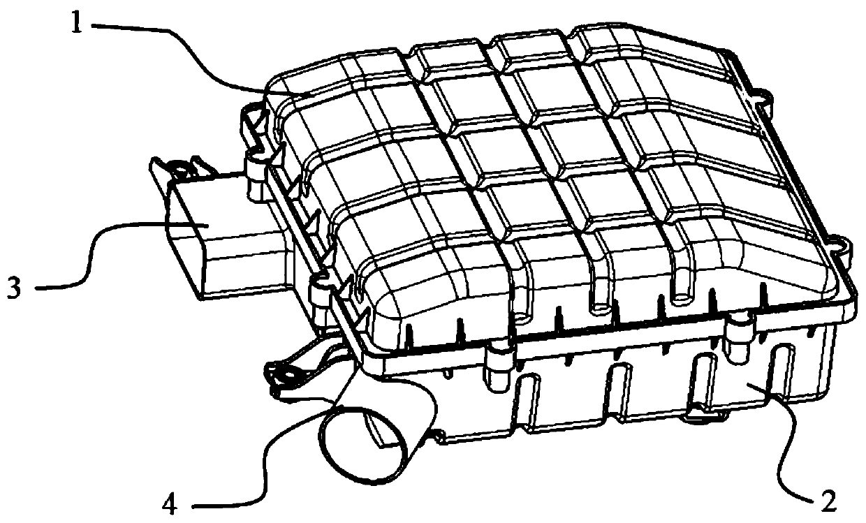
[0029] like figure 1 As shown, the automobile air filter includes an upper air filter housing 1 and a lower air filter housing 2. The upper air filter housing 1 and the lower air filter housing 2 are connected by eight corresponding bolt holes, and each side is connected by two bolt holes. Bolt holes are secured.

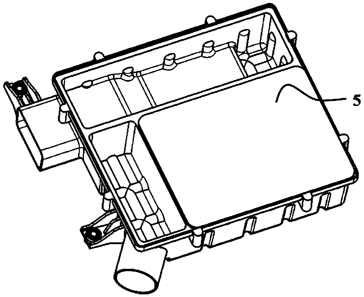
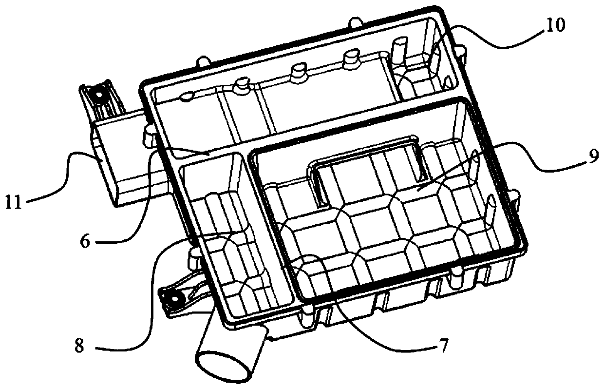
[0030] like figure 2 , 3 The shown air filter lower housing 2 is divided into a resonant cavity 10, a filter chamber 9 and an air outlet chamber 8 by a longitudinal partition plate 6 and a transverse partition plate 7, that is, the air filter lower housing 2 is separated by a longitudinal partition plate 6 , wherein the part with a smaller area is the resonant cavity 10, and the part with a larger area is divided into a filter chamber 9 and an air outlet chamber 8 by a transverse partition plate 7. Air enters through the air filter air inlet 3 and passes through the air inlet chamber 11 , the resonant cavity 10 , the filter chamber 9 , and the air outlet chamber...


PUM


Abstract

The invention discloses an automobile air filter structure which comprises an air filtering upper shell and an air filtering lower shell. The air filtering lower shell is provided with an air inlet chamber, a resonant cavity, a filtering chamber and an air outlet chamber; an air filtering air inlet is formed in the air inlet chamber; an air filtering air outlet is formed in the air outlet chamber; a filtering element is arranged in the filtering chamber; air enters through the air filtering air inlet, sequentially passes through the air inlet chamber, the resonant cavity, the filtering chamber and the air outlet chamber, and is discharged through the air filtering air outlet; the air inlet chamber is a channel placed in the resonant cavity; and one end of the air inlet chamber is the air filtering air inlet, and the other end of the air inlet chamber is provided with a connecting hole communicating with the resonant cavity. According to the automobile air filter structure, by lowering the body height of an air filter, damage caused by vibration can be effectively reduced, meanwhile, the automobile air filter structure has the characteristics of being compact in structure, small in mounting space and good in stiffness, and the purpose of improving air inlet noise can be achieved.

Description

technical field [0001] The invention relates to the technical field of automobile power devices, in particular to an automobile air filter. Background technique [0002] Undoubtedly, noise has become a major public nuisance affecting people's comfortable life, and the automotive industry is no exception. While ensuring other performances of automobiles, major automobile manufacturers also pay great attention to the improvement of NVH performance of automobiles. The noise of the intake system is one of the sources that affect the noise of the car, and the air filter acts as a portal for the air to enter the engine. The expansion muffler has the effect of reducing intake noise. For this reason, the noise reduction design of the air filter is very important. [0003] Most of the air filters are designed with a simple cavity structure. Generally, a single circular pipe is used to enter and exit the air, and there is no obvious change in the cross section. Therefore, the acous...

Claims


Application Information

Patent Timeline
Patent Type & Authority Patents(China)
IPC IPC(8): F02M35/024F02M35/02F02M35/12
CPCF02M35/0201F02M35/0202F02M35/024F02M35/1266
Inventor 卞晨
Owner CHERY AUTOMOBILE CO LTD
Learn More