Vehicle with air deflector for wheel

An air deflector, wheel technology, applied in vehicle components, aerodynamic improvement, body and other directions, can solve problems such as high cost and reliability

Active Publication Date: 2017-08-29
PEZHO SITROEN AUTOMOBILS SA
View PDF10 Cites 5 Cited by
  • Summary
  • Abstract
  • Description
  • Claims
  • Application Information

AI Technical Summary

Problems solved by technology

Additionally, the taught solution may introduce reliability issues and have higher cost

Method used


Image

  • Vehicle with air deflector for wheel
  • Vehicle with air deflector for wheel
  • Vehicle with air deflector for wheel

Examples


Embodiment Construction

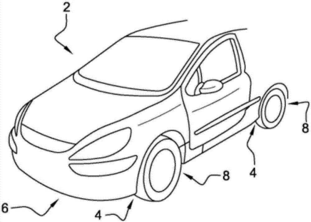
[0028] figure 1 is a perspective view of a motor vehicle 2 including an air deflector 4 according to the invention. The underside 6 of the motor vehicle 2 includes wheel tunnels 8 at the front and rear of the vehicle. The air deflector 4 is located in front and / or behind the wheel, thereby reducing the aerodynamic drag of the wheel. The air deflectors also change the air flow in the wheel wells.

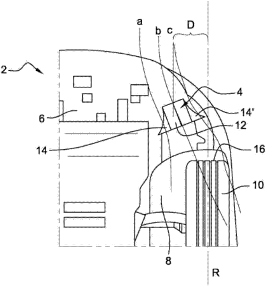
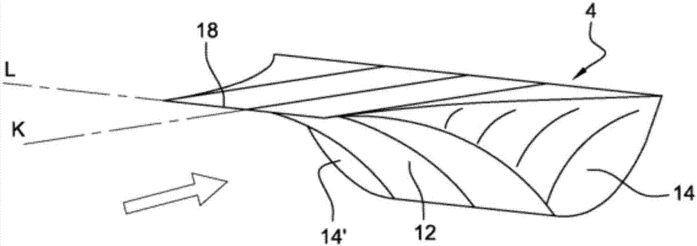
[0029] figure 2 is a view of the underside 6 of the motor vehicle 2 according to the invention. The wheels 10 arranged in the wheel tunnel 8 at the front left of the vehicle 2 can be seen exactly. In this case, the air deflector 4 according to the invention is located in front of the wheel tunnel 8 . The air deflector 4 includes a front face 12 and side faces 14 and 14' arranged to deflect air downward and sideways of the wheel. It can be seen that the air deflector 4 is at a distance from the front face 16 of the wheel, which distance is less than 300 mm, preferably less than...


PUM

PropertyMeasurementUnit
Maximum heightaaaaaaaaaa

Abstract

The invention relates to an air deflector (4) intended to be mounted under a motor vehicle, in front of a wheel of said vehicle, with a view to reduce the aerodynamic drag at said wheel, wherein said air deflector (4) comprises: an angled front surface (12) having a concave profile ; two side surfaces (14; 14') on either side of the front surface (12), respectively; wherein at least one of the two side surfaces (14; 14') has a concave profile. The invention also relates to a vehicle comprising at least one such air deflector (4).

Description

technical field [0001] The invention relates to the aerodynamic properties of motor vehicles. More specifically, the present invention relates to reducing the aerodynamic drag of motor vehicles. Background technique [0002] Below a motor vehicle is usually an area of ​​resistance through which the vehicle travels through the air. At high speeds, drag results primarily from the aerodynamic forces exerted on the vehicle passing through areas of air overpressure and air pressure drop, for example by flow splitting or partial counterflow. These aerodynamic forces are opposed to vehicle travel. In particular, the wheels of a motor vehicle exert an air overpressure on their fronts that creates drag resistance. In addition, air flow is often flooded into the wheel tunnels, and air splits can be observed downstream of these wheel tunnels. Since aerodynamic drag does negative work in the energy balance of the vehicle, which leads to an increase in fuel consumption, it is therefo...

Claims


Application Information

Patent Timeline
IPC IPC(8): B62D35/02
CPCB62D35/02B62D35/005Y02T10/82Y02T10/88
Inventor 格里戈里·普雅尔托尼·鲁伊斯珍妮-菲利普·泰凡
Owner PEZHO SITROEN AUTOMOBILS SA
Why Eureka
Try Eureka