
Dual-camera scanning gun and scanning method thereof

A dual-camera, scanning method technology, applied in the field of barcode scanning, can solve problems such as limited scope of application, and achieve the effects of improving the use sensitivity, expanding the use distance range, and shortening the scanning time

Active Publication Date: 2021-04-06
FUJIAN LANDI COMML EQUIP CO LTD
View PDF7 Cites 0 Cited by
  • Summary
  • Abstract
  • Description
  • Claims
  • Application Information

AI Technical Summary

Problems solved by technology

This patent also uses dual cameras to obtain the first image and the second image, and finally stitches the two images together, so the depth of field of the first camera and the second camera should also be consistent, and the scope of application is also limited

Method used


Image

  • Dual-camera scanning gun and scanning method thereof
  • Dual-camera scanning gun and scanning method thereof
  • Dual-camera scanning gun and scanning method thereof

Examples


Embodiment 1

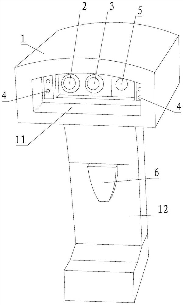
[0055] Please refer to figure 1 , Embodiment 1 of the present invention is:

[0056] A dual-camera scanning gun, including a housing 1, also includes a near-focus camera 2 and a far-focus camera 3, the housing 1 is provided with a scanning window 11, and the near-focus camera 2 and the far-focus camera 3 are installed on the At the scanning window 11, the near-focus camera 2 and the far-focus camera 3 are horizontally arranged side by side. It is convenient to align the near-focus camera 2 and the far-focus camera 3 at the barcode to be scanned at the same time.

Embodiment 2

[0057] Please refer to figure 1 , the second embodiment of the present invention is:

[0058] A dual-camera scanning gun, on the basis of Embodiment 1, further includes a supplementary light 4, a laser positioning light 5, a light grid, a buzzer, and a scanning button 6, and the supplementary light 4 is installed on the housing 1 at the scanning window 11; preferably, the supplementary light 4 is symmetrically installed at the left and right edges of the scanning window 11 of the housing 1; the laser positioning lamp 5 is installed at the scanning window 11 of the housing 1 place; the laser positioning light 5 is installed between the near-focus camera 2 and the far-focus camera 3, or the laser positioning light 5 is installed on the outer side of the near-focus camera 2 or the outer side of the far-focus camera 3, The laser positioning lamp 5 is a high-brightness infrared focusing LED lamp, and the light grid is installed in front of the laser positioning lamp 5; the buzzer ...

Embodiment 3

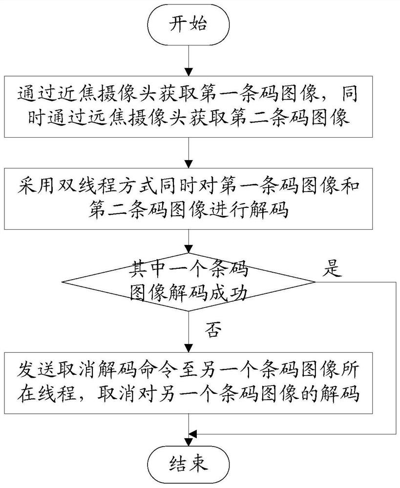
[0096] Please refer to figure 2 , Embodiment three of the present invention is:

[0097] A dual-camera scanning gun scanning method, the method is:

[0098] Obtain the first barcode image through the near-focus camera, and obtain the second barcode image through the far-focus camera at the same time;

[0099] Decode the first barcode image and the second barcode image, specifically:

[0100] Simultaneously decode the first barcode image and the second barcode image in a dual-thread manner;

[0101] After one barcode image in the first barcode image and the second barcode image is successfully decoded, a cancel decoding command is sent to the thread where the other barcode image is located to cancel the decoding of the other barcode image.


PUM


Abstract

The present invention provides a dual-camera scanning gun and a scanning method for the dual-camera scanning gun, which include a casing, a near-focus camera and a far-focus camera. The casing is provided with a scanning window, and the near-focus camera and the far-focus camera are installed at the scan window. The method is as follows: acquiring the first barcode image through a close-focus camera, and simultaneously acquiring the second barcode image through a far-focus camera; and decoding the first barcode image and / or the second barcode image. The barcode image is obtained by the near-focus camera and the far-focus camera with different depths of field, and the barcode image is decoded to expand the use range of the scanning gun, reduce the time of manual adjustment of the scanning gun, reduce the scanning time of the scanning gun, and improve the scanning sensitivity .

Description

technical field [0001] The invention relates to the technical field of barcode scanning, in particular to a dual-camera scanning gun and a scanning method thereof. Background technique [0002] In order to expand the payment function of the cash register system such as POS machines and cash register computers, a barcode scanning gun is connected to the cash register system terminal to scan and decode barcodes to realize fast code scanning payment. Existing barcode scanning guns all use a camera to scan codes, and a camera only has a fixed depth of field range. According to the needs of customers, install a camera with a suitable depth of field. Usually the depth of field of the camera ranges from 3 to 100mm, or 50 to 100mm, which limits the scope of use of a single scanner. [0003] The Chinese invention patent with the publication number CN103861275A discloses an improved scanning device design. A scanning device has multiple cameras. The error of one or more previous sca...

Claims


Application Information

Patent Timeline
Patent Type & Authority Patents(China)
IPC IPC(8): G06K7/10G06K7/14
CPCG06K7/10881G06K7/1408G06K2007/10524
Inventor 吴卫东刘礼建
Owner FUJIAN LANDI COMML EQUIP CO LTD
Learn More