
Nozzle-position-adjustable sand blasting machine

A sand blasting machine, adjustable technology, applied in the direction of spray guns, explosion generating devices, abrasives, etc., can solve the problems of insufficient adaptability to different workpieces, time-consuming and labor-intensive, and large investment in tooling costs, and achieve small sliding friction, firm fixation, Ease of processing

Inactive Publication Date: 2017-09-01
肇庆市端州区麒诺机械科技有限公司
View PDF6 Cites 0 Cited by
  • Summary
  • Abstract
  • Description
  • Claims
  • Application Information

AI Technical Summary

Problems solved by technology

Due to the different shapes and positions of the inner cavities of different castings, the position of the nozzle needs to be adjusted during sandblasting to optimize the angle and distance of the spray to adapt to various workpieces. At present, fully automatic sandblasting machines use Fixed nozzles are not adaptable enough to different workpieces, and different nozzle fixing fixtures need to be replaced for different workpieces
In order to complete the adjustment of the position and angle of the nozzle, it is time-consuming and labor-intensive to replace the fixed tooling of the nozzle, and the cost of the tooling is large.

Method used


Image

  • Nozzle-position-adjustable sand blasting machine
  • Nozzle-position-adjustable sand blasting machine

Examples


Embodiment 1

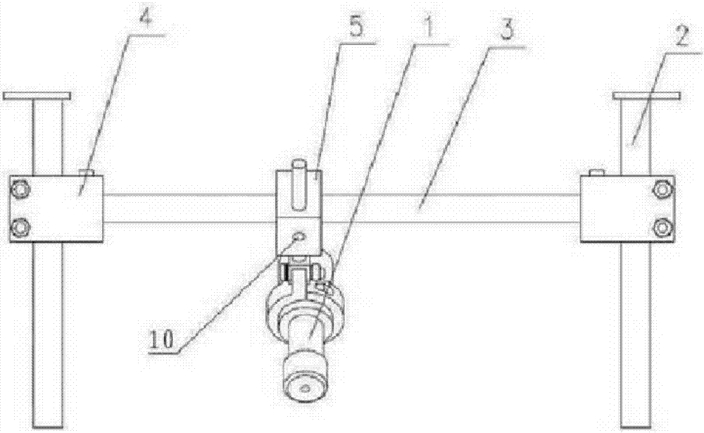
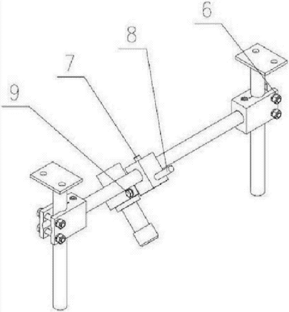
[0017] Example 1 consists of Figure 1-2 It can be seen from the illustrated embodiment that this embodiment includes a nozzle 1 located in the chamber of the sandblasting machine, the nozzle 1 is connected to the inner wall of the chamber through a nozzle position adjustment mechanism, and the nozzle position adjustment mechanism includes two cylindrical vertical sliding guide rails 2 arranged side by side and a cylindrical horizontal sliding guide rail 3, one end of two vertical sliding guide rails 2 is fixed to the inner wall of the chamber, and the two ends of the horizontal sliding guide rail 3 are connected to the vertical sliding guide rail through the first slider 4 matched with the vertical sliding guide rail 2 respectively. 2 Sliding connection, a locking and positioning device is provided on the two first sliders 4: the first slider 4 is provided with an opening sliding hole matching the cylinder, and a locking locking device is provided at the opening end of the ope...

Embodiment 2

[0018] Embodiment 2 The basic structural principle of Embodiment 2 is the same as that of Embodiment 1, except that the direction is adjusted, and no drawings are shown here.

[0019] Including the nozzle located in the chamber of the sand blasting machine, the nozzle is connected with the inner wall of the chamber through the nozzle position adjustment mechanism, the nozzle position adjustment mechanism includes a cylindrical vertical sliding guide rail and two cylindrical horizontal sliding guide rails arranged side by side, and the two horizontal sliding guide rails One end is fixed to the inner wall of the chamber, and the two ends of the vertical sliding guide rail are slidingly connected with the horizontal sliding guide rail through the first slider matched with the horizontal sliding guide rail respectively, and locking and positioning devices are provided on the two first sliders ; The locking and positioning device on the first slider includes: the first slider is pro...


PUM


Abstract

The invention discloses a nozzle-position-adjustable sand blasting machine comprising a nozzle located in a sand blasting machine room body; the nozzle is connected with the inner wall of the room body by a nozzle position adjusting mechanism; the nozzle position adjusting mechanism comprises a vertically-sliding guide rail and a horizontally-sliding guide rail; one end of the vertically-sliding guide rail is fixed together with the inner wall of the room body; one end of the horizontally-sliding guide rail is slidably connected with the vertically-sliding guide rail by a first slide block adapted with the vertically-sliding guide rail; the first slide block is provided with a locking and locating device; the horizontally-sliding guide rail is slidably connected with the nozzle by a second slide block adapted with the horizontally-sliding guide rail; and the second slide block is provided with a locking and locating device. The nozzle-position-adjustable sand blasting machine has the characteristic of spraying position and angle adjustability and can be used for cleaning different workpieces so as to be wide in adaptability.

Description

technical field [0001] The invention relates to a sandblasting machine with adjustable nozzle position. Background technique [0002] The fully automatic sandblasting machine completes the cleaning of the casting surface. The inner cavity of the casting often has oxide scales and attachments that are not easy to clean. It needs to be aligned with the nozzle and the inner cavity to clean. Due to the different shapes and positions of the inner cavities of different castings, the position of the nozzle needs to be adjusted during sandblasting to optimize the angle and distance of the spray to adapt to various workpieces. At present, fully automatic sandblasting machines use Fixed nozzles are not adaptable enough to different workpieces, and different nozzle fixing fixtures need to be replaced for different workpieces. In order to complete the adjustment of the position and angle of the nozzle, it is time-consuming and labor-intensive to replace the fixed tooling of the nozzle,...

Claims


Application Information

Patent Timeline
Patent Type & Authority Applications(China)
IPC IPC(8): B24C5/04
CPCB24C5/04
Inventor 江钰琪
Owner 肇庆市端州区麒诺机械科技有限公司
Learn More