
Supersonic spraying pipe

A supersonic and nozzle technology, applied in the direction of jet propulsion devices, machines/engines, etc., can solve the problems of high processing difficulty, total gas pressure loss, lack of economy and environmental protection, etc., and achieve production difficulty and cost reduction Effect

Pending Publication Date: 2017-09-01
BEIJING AEROSPACE SANFA HIGH TECH
View PDF9 Cites 8 Cited by
  • Summary
  • Abstract
  • Description
  • Claims
  • Application Information

AI Technical Summary

Problems solved by technology

[0002] With the maturity of the engine, the application of supersonic engines is becoming more and more extensive. On this basis, the use of supersonic nozzles is involved in the use of supersonic nozzles for aircraft, especially unmanned aerial vehicles, and ground tests of engines. In the supersonic nozzle in the sense, its internal flow channel needs to meet the geometric parameters of the flow channel of the Laval nozzle, while in the traditional sense of the Laval nozzle, the surface of the flow channel changes complicatedly, and the processing is extremely difficult, resulting in cost In the existing technology, in order to reduce the cost and realize the mass production of the supersonic nozzle, the internal flow channel of the supersonic nozzle is simplified from the curved surface of the Laval nozzle to the internal flow channel fixedly connected in sequence For the converging section of the converging circular table surface, the internal flow channel is the straight section of the cylindrical surface and the internal flow channel is the expanding section of the expanding circular table surface. Although this reduces the cost, the setting of the straight line converging section and the expanding section leads to a significant increase in the total pressure of the gas. Loss, not economical and environmentally friendly

Method used


Image

  • Supersonic spraying pipe
  • Supersonic spraying pipe

Examples


Embodiment Construction

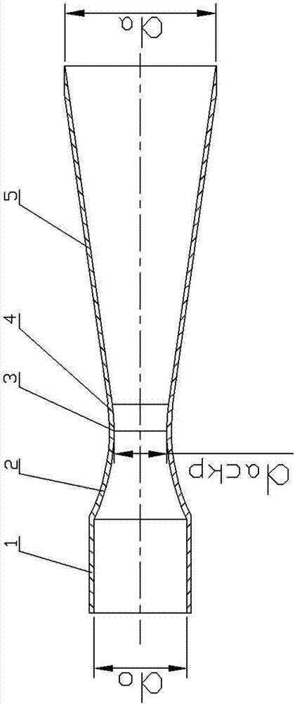
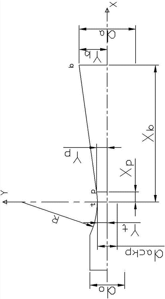
[0023] Such as Figure 1-2 As shown, a supersonic nozzle includes an inlet equal straight section 1, a subsonic convergent section 2, an initial supersonic expansion section 4 and a supersonic expansion section 5 that are fixedly connected in sequence; the inlet equal straight section 1, The subsonic convergence section 2, the initial supersonic expansion section 4 and the supersonic expansion section 5 are all hollow bodies of revolution, and the entrance is straight section 1, the subsonic convergence section 2, the initial supersonic expansion section 4 and the supersonic expansion section 5 The axis of revolution of the same; the internal flow channel of the subsonic convergence section 2 is a continuously shrinking circular arc axis of revolution, and the internal flow channel of the initial supersonic expansion section 4 is a continuously expanding circular axis surface of revolution, The internal flow channel of the supersonic expansion section 5 is a circular table sur...


PUM


Abstract

Disclosed is a supersonic spraying pipe. An inlet equal straight section, a subsonic convergent section, an initial supersonic expansion section and a supersonic expansion section which are fixedly connected are all hollow rotation bodies with the same rotation axis. An internal flow channel of the subsonic convergent section is a continuous contracting arc axis rotation curve surface. An internal flow channel of the initial supersonic expansion section is a continuous expanding arc axis rotation curve surface. An internal flow channel of the supersonic expansion section is a circular truncated cone surface. The radius of the arc of the subsonic convergent section is the same as the radius of the arc of the initial supersonic expansion section. The connection section of the internal flow channels of the subsonic convergent section and the initial supersonic expansion section is the section of a throat. The generatrix of the internal flow channel circular truncated cone of the supersonic expansion section and the tail end of the internal flow channel continuous expanding arc of the initial supersonic expansion section are tangent. According to the supersonic spraying pipe, under the situation that it is guaranteed that the gas total pressure loss of the supersonic spraying pipe and the gas total pressure loss of a traditional laval spraying pipe are basically same, manufacturing difficulty and the manufacturing cost are reduced by a large margin, mass production of the supersonic spraying pipes can be achieved.

Description

technical field [0001] The invention relates to a nozzle, in particular to a supersonic nozzle. Background technique [0002] With the maturity of the engine, the application of supersonic engines is becoming more and more extensive. On this basis, the use of supersonic nozzles is involved in the use of supersonic nozzles for aircraft, especially unmanned aerial vehicles, and ground tests of engines. In the supersonic nozzle in the sense, its internal flow channel needs to meet the geometric parameters of the flow channel of the Laval nozzle, while in the traditional sense of the Laval nozzle, the surface of the flow channel changes complicatedly, and the processing is extremely difficult, resulting in cost In the existing technology, in order to reduce the cost and realize the mass production of the supersonic nozzle, the internal flow channel of the supersonic nozzle is simplified from the curved surface of the Laval nozzle to the internal flow channel fixedly connected in...

Claims


Application Information

Patent Timeline
IPC IPC(8): F02K1/40
CPCF02K1/40
Inventor 孙晓彤赵聚钧
Owner BEIJING AEROSPACE SANFA HIGH TECH
Learn More