
Internal water pressure loading device for water tunnel structure model test

A model test, tunnel structure technology, applied in the direction of measuring devices, using stable tension/pressure testing materials, instruments, etc., can solve the problems of sewage overflow pollution, no deep tunnel drainage works, flood disasters, etc., to ensure The effect of construction and operation safety, small error and low reliability

Active Publication Date: 2017-09-01
SOUTHWEST JIAOTONG UNIV
View PDF21 Cites 8 Cited by
  • Summary
  • Abstract
  • Description
  • Claims
  • Application Information

AI Technical Summary

Problems solved by technology

[0002] In recent years, the long-term pressurized operation of sewage pipe networks in many cities, serious overflow pollution of sewage, and frequent flood disasters have highlighted that the drainage pipe networks of most cities in my country can no longer meet the needs of urban development. Reconstruction, expansion and new drainage system imminent
Urban deep tunnel drainage has been used for many years in some countries, such as the drainage system in Tokyo, Japan, the urban drainage system in Paris, France, and the deep tunnel sewage system in Singapore. Except for the Lai Chi Kok rainwater deep tunnel system, there is no deep tunnel drainage project. In recent years, with the proposal of the concept of sponge city in my country, the deep drainage of cities such as Guangzhou, Wuhan and Chengdu is being planned, designed and constructed.

Method used


Image

  • Internal water pressure loading device for water tunnel structure model test
  • Internal water pressure loading device for water tunnel structure model test

Examples


Embodiment

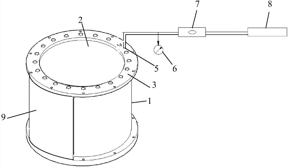
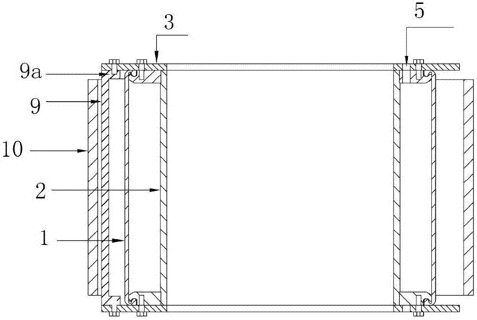
[0019] Figure 1-2 It is shown that a specific embodiment of the present invention is an internal water pressure loading device used for the structural model test of a water conveyance tunnel, comprising two parts: a rubber air bag pressurizing device and an air supply and pressure maintaining device, in which:

[0020] The rubber airbag pressurizing device is composed of: an outer rubber wall 1, an inner stainless steel wall 2, and a stainless steel flange ring 3 at the upper and lower ends to form a circular cylindrical airbag; the stainless steel flange An air hole 5 is provided on the ring 3;

[0021] The composition of the gas supply and pressure holding device is: CO 2 The gas source 8, the three-position rotary valve 7, the barometer 6, and the gas hole 5 are connected in sequence by a gas pipe.

[0022] The outer edge of the stainless steel flange ring 3 in this example protrudes from the outer surface of the rubber wall 1. The upper and lower sides of the stainless steel ar...


PUM


Abstract

The invention discloses an internal water pressure loading device for a water tunnel structure model test. The internal water pressure loading device comprises two parts, namely a rubber airbag pressurization device and an air supply and pressure maintaining device, wherein the structure of the rubber airbag pressurization device is as follows: a circular cylindrical airbag is formed by a rubber wall on the outer side, a stainless steel on the outer side, and stainless steel flange rings at the upper and lower ends in a sealed manner; air transmission holes are formed in the stainless steel flange rings; the air supply and pressure maintaining device has the structure that: a CO2 source, a three-position rotary valve, a gas-pressure meter and the air transmission holes are sequentially connected with one another. According to the device disclosed by the invention, the tunnel model can be subjected to internal water pressure loading, and the effect and influence of the internal water pressure on the tunnel structure are simulated. When matched with the existing tunnel external water and soil pressure loading device, the device can simulate the mechanical properties and failure modes of a water tunnel in a tunnel lining under the actions of different internal water pressures and external water and soil pressure loads, so that a scientific and reliable test basis can be provided for structural design and construction of the water tunnel. Therefore, the construction and operation safety of the tunnel can be guaranteed.

Description

Technical field [0001] The invention belongs to the technical field of civil engineering, and particularly relates to the technical field of water conveyance tunnel model tests. Background technique [0002] In recent years, the sewage pipe network in many cities has been operating under pressure for a long time, the serious overflow pollution of sewage and the frequent flood disasters have highlighted that the drainage pipe network of most cities in my country can no longer meet the needs of urban development. Reconstruction, expansion and new drainage The system is imminent. Urban deep tunnel drainage has been used for many years in some countries, such as the Tokyo Circle Drainage System in Japan, the Paris Urban Drainage System in France, and the Deep Tunnel Sewage System in Singapore, etc., which give full play to the functions of flood prevention and drainage and overflow pollution control. Outside the Lai Chi Kok rainwater deep tunnel system, there is no deep tunnel drainag...

Claims


Application Information

Patent Timeline
IPC IPC(8): G01N3/12
CPCG01N3/12G01N2203/0048
Inventor 郭瑞何川谢宏明罗冬冬
Owner SOUTHWEST JIAOTONG UNIV
Learn More