
Medical test tube inner wall cleaning device

A cleaning device and a technology in a test tube, applied in the medical field, can solve the problems of increasing labor costs, reasonably controlling the rotational speed, failing to meet the use requirements of the laboratory department, etc., and achieve the effect of fixing and stable and improving the cleaning effect.

Inactive Publication Date: 2017-09-05
CHANGSHA WUDAO IND DESIGN CO LTD
View PDF0 Cites 33 Cited by
  • Summary
  • Abstract
  • Description
  • Claims
  • Application Information

AI Technical Summary

Problems solved by technology

[0002] Hospital laboratories need to use a large number of test tubes, and it takes a lot of manpower to clean these test tubes every day. In the prior art, the method of hand brushing is usually used to clean the test tubes one by one. On the one hand, the labor cost is increased. On the other hand, the efficiency also very low
Although there are a lot of cleaning equipment for test tube scrubbing, they cannot meet the requirements of the laboratory. Most of the existing cleaning equipment basically uses cleaning brushes to clean the inside of the test tube and can only do horizontal cleaning. However, for some stubborn stains, it needs to be cleaned. The expected cleaning effect can only be achieved by cross-cleaning it horizontally and vertically, and if a motor is used instead of manual cleaning, the speed cannot be reasonably controlled according to the actual situation, which will cause damage to the inner wall of the test tube, resulting in a higher scrapping rate of the test tube

Method used


Image

  • Medical test tube inner wall cleaning device
  • Medical test tube inner wall cleaning device
  • Medical test tube inner wall cleaning device

Examples


Embodiment Construction

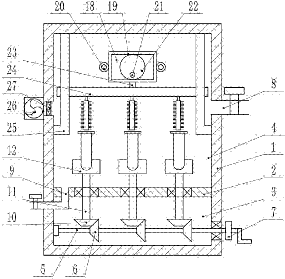
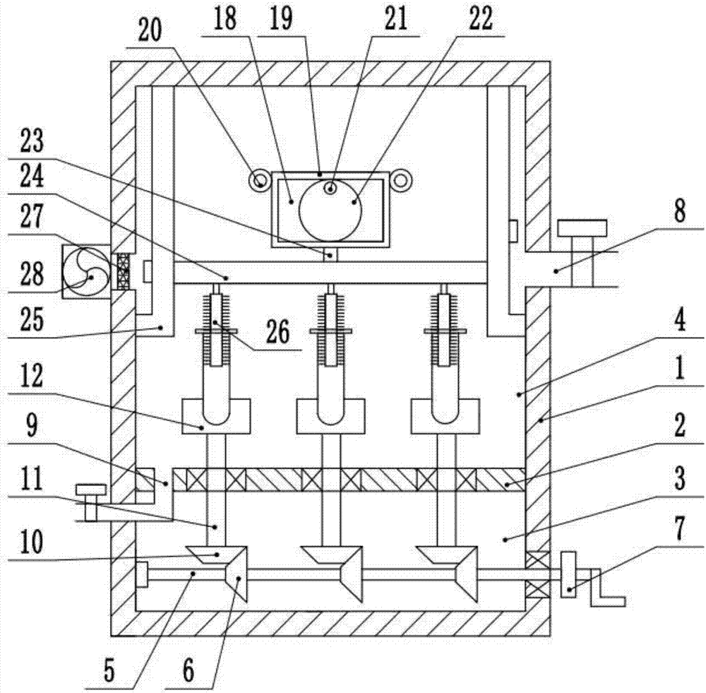
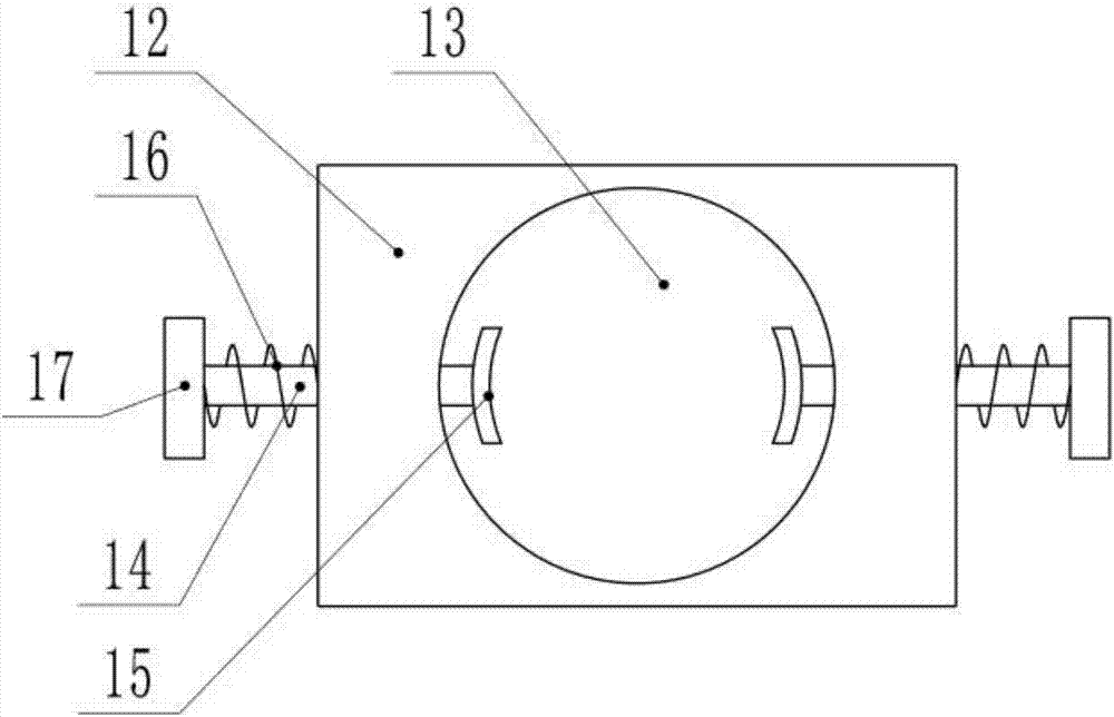
[0020] The technical scheme of this patent is described in further detail below in conjunction with specific embodiments

[0021] see Figure 1-4 , a medical test tube inner wall cleaning device, comprising a device cavity 3, a cleaning cavity 4, a bevel gear A6, a bevel gear B10, a fixed frame 12, a lifting device 18, a cleaning brush 26 and an air inlet 27, the inside of the device body 1 A partition 2 is installed horizontally, and the partition 2 divides the interior of the device body 1 into a device chamber 3 and a cleaning chamber 4. A rotating shaft A5 is installed horizontally in the device chamber 3, and a bearing is connected between the left end of the rotating shaft A5 and the inner wall of the device body 1. , the right end of the rotating shaft A5 passes out of the device body 1, and the right end of the rotating shaft A5 is also connected with the casing of the device body 1 through a bearing. Several groups of bevel gears A6 are also concentrically installed,...


PUM

PropertyMeasurementUnit
Depthaaaaaaaaaa

Abstract

The invention discloses a device for cleaning the inner wall of a medical test tube, comprising a device cavity, a cleaning cavity, a bevel gear A, a bevel gear B, a fixing frame, a lifting device, a cleaning brush and an air inlet. The interior of the device body is horizontally installed with a partition The baffle plate divides the inside of the device body into a device cavity and a cleaning cavity, a fixing frame is fixedly installed on the upper end of the rotating shaft B, a lifting device is installed in the device body, and several groups of cleaning brushes are fixedly installed on the lower side of the sliding plate. By setting the fixing frame, the test tube can be clamped to prevent the test tube from being thrown out due to centrifugal force during the rotation process, and at the same time, the anti-slip leather pad is added on the fixing claw to increase its friction to make the test tube more stable; Since the test tube starts to rotate by manually shaking the wheel, the cleaning brush cleans the inner wall of the test tube horizontally, and at the same time, the cleaning brush moves up and down to clean the vertical stains on the inner wall of the test tube to improve the cleaning effect.

Description

technical field [0001] The invention relates to the medical field, in particular to a cleaning device for the inner wall of a medical test tube. Background technique [0002] Hospital laboratories need to use a large number of test tubes, and it takes a lot of manpower to clean these test tubes every day. In the prior art, the method of hand brushing is usually used to clean the test tubes one by one. On the one hand, the labor cost is increased. On the other hand, the efficiency Also very low. Although there are a lot of cleaning equipment for test tube scrubbing, they cannot meet the requirements of the laboratory. Most of the existing cleaning equipment basically uses cleaning brushes to clean the inside of the test tube and can only do horizontal cleaning. However, for some stubborn stains, it needs to be cleaned. The expected cleaning effect can only be achieved by cross-cleaning it horizontally and vertically, and if a motor is used instead of manual cleaning, the spe...

Claims


Application Information

Patent Timeline
IPC IPC(8): B08B9/087B08B13/00F26B21/00
CPCB08B9/0808B08B9/0821B08B13/00F26B21/00
Inventor 吴小明
Owner CHANGSHA WUDAO IND DESIGN CO LTD
Features
  • Generate Ideas
  • Intellectual Property
  • Life Sciences
  • Materials
  • Tech Scout
  • Unparalleled Data Quality
  • Higher Quality Content
  • 60% Fewer Hallucinations
Learn More