A station adjustable fixture device for imprinting T-joint workpieces

A fixture device and station technology, applied in the field of station-adjustable fixture devices, can solve problems such as inaccurate experimental data and position deviation of embossed points, and achieve the effects of avoiding manual support, avoiding errors, and ensuring safety

Active Publication Date: 2019-04-09
KUNMING UNIV OF SCI & TECH
View PDF12 Cites 0 Cited by
  • Summary
  • Abstract
  • Description
  • Claims
  • Application Information

AI Technical Summary

Problems solved by technology

[0004] The invention provides a position-adjustable fixture device for embossing a T-shaped joint workpiece, so as to solve the problems of position deviation of embossing points and inaccurate experimental data in the existing embossing process

Method used


Image

  • A station adjustable fixture device for imprinting T-joint workpieces
  • A station adjustable fixture device for imprinting T-joint workpieces
  • A station adjustable fixture device for imprinting T-joint workpieces

Examples


Embodiment 1

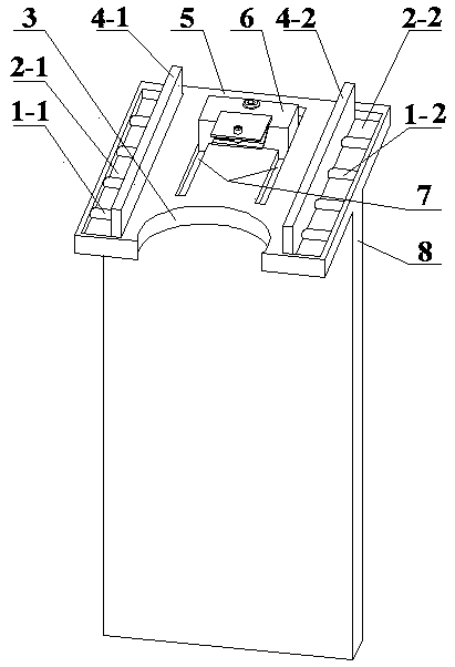
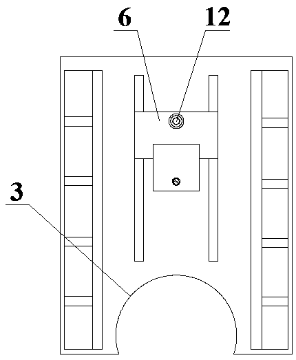
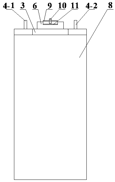
[0021] Embodiment 1: as Figure 1-5 As shown, a position-adjustable fixture device for embossing T-shaped joint workpieces, including spring group Ⅰ1-1, spring group Ⅱ1-2, centering plate groove Ⅰ2-1, centering plate groove Ⅱ2-2, ring Set 3, centering plate Ⅰ4-1, centering plate Ⅱ4-2, clamp body 5, positioning block 6, baffle groove 7, vertical plate 8, upper pressing plate 9, adjusting screw 10, lower pressing plate 11, fastening screw 12 and graduated scale 13;

[0022] The vertical plate 8 is connected to the lower end of the fixture main body 5, the centering plate groove I2-1 and the centering plate groove II2-2 are respectively milled on both sides of the upper end of the fixture main body 5, and the baffle plate groove 7 is milled out in the middle of the upper end of the fixture main body 5, The front end of the clamp body 5 is provided with a ring sleeve 3, the spring group I1-1 is located in the centering plate groove I2-1, the spring group II1-2 is located in the c...

Embodiment 2

[0035] Embodiment 2: as Figure 1-5 As shown, a position-adjustable fixture device for embossing T-shaped joint workpieces, including spring group Ⅰ1-1, spring group Ⅱ1-2, centering plate groove Ⅰ2-1, centering plate groove Ⅱ2-2, ring Set 3, centering plate Ⅰ4-1, centering plate Ⅱ4-2, clamp body 5, positioning block 6, baffle groove 7, vertical plate 8, upper pressing plate 9, adjusting screw 10, lower pressing plate 11, fastening screw 12 and graduated scale 13;

[0036] The vertical plate 8 is connected to the lower end of the fixture main body 5, the centering plate groove I2-1 and the centering plate groove II2-2 are respectively milled on both sides of the upper end of the fixture main body 5, and the baffle plate groove 7 is milled out in the middle of the upper end of the fixture main body 5, The front end of the clamp body 5 is provided with a ring sleeve 3, the spring group I1-1 is located in the centering plate groove I2-1, the spring group II1-2 is located in the c...


PUM


Abstract

The invention relates to a station-adjustable clamp device for T-shaped joint workpiece embossment and belongs to the field of clamp design. A vertical plate is connected with the lower end of a clamp body. Centring plate grooves are milled in the two sides of the upper end of the clamp body. A baffle groove is milled in the middle of the upper end of the clamp body. A circular ring sleeve is arranged at the front end of the clamp body. A spring set is located in each centring plate groove. One end of each spring seat is connected with the outer side of the corresponding centring plate groove. The other end of each spring set is connected with the outer side of the corresponding centring plate, and each centring plate is pressed on the inner side of the corresponding centring plate groove; a positioning block slides in the baffle groove, a fastening screw is fixed to the positioning block and used for fixing the positioning block to the clamp body, the positioning block is fixedly provided with an upper press plate and a lower press plate, and an adjusting screw is arranged on the positioning block and used for adjusting the downward-press depth of the lower press plate. By the adoption of the station-adjustable clamp device for the T-shaped joint workpiece embossment, the embossment point position can be positioned precisely, and the distance can be monitored in real time; the centring reliability is guaranteed effectively; and the state of the separation from the manual holding in the embossment can be achieved.

Description

technical field [0001] The invention relates to a position-adjustable fixture device for embossing a T-shaped joint workpiece, in particular to a device capable of precisely locating the embossing point and having an automatic centering function, which belongs to the field of fixture design. Background technique [0002] Embossing connection technology is a connection molding method that relies on plastic deformation of materials, which can effectively realize the connection of same, different, multi-layer and interlayer sheets. In the process of embossing connection, the material to be connected first goes down with the upper mold, and the material begins to deform in the lower mold, and at the same time, the movable part of the lower mold is opened outwards, fully deformed in the cavity, and the embossing connection is completed. [0003] Compared with other conventional plate connection methods, embossing connection technology has the advantages of high dynamic fatigue st...

Claims


Application Information

Patent Timeline
Patent Type & Authority Patents(China)
IPC IPC(8): B21D43/00
CPCB21D43/00
Inventor 何晓聪刘佳沐
Owner KUNMING UNIV OF SCI & TECH
Why Eureka
Try Eureka