Buffering limiting lift car

An elevator car and position-limiting technology, which is applied to elevators in buildings, non-rotational vibration suppression, transportation and packaging, etc., can solve the problems of no buffer mechanism, passengers shaking up and down, and unsatisfactory riding effects, etc., and achieve improvement Lifting effect, effect of preventing shock and vibration

Inactive Publication Date: 2017-09-05
江苏奥菱电梯有限公司
View PDF5 Cites 5 Cited by
  • Summary
  • Abstract
  • Description
  • Claims
  • Application Information

AI Technical Summary

Problems solved by technology

[0004] In the existing elevator car, the bottom surface is generally not equipped with a buffer mechanism, and the buffer generated when the elevator goes up and down will easily cause the passengers in the car to feel up and down, and the riding effect is not ideal.

Method used


Image

  • Buffering limiting lift car
  • Buffering limiting lift car

Examples


Embodiment Construction

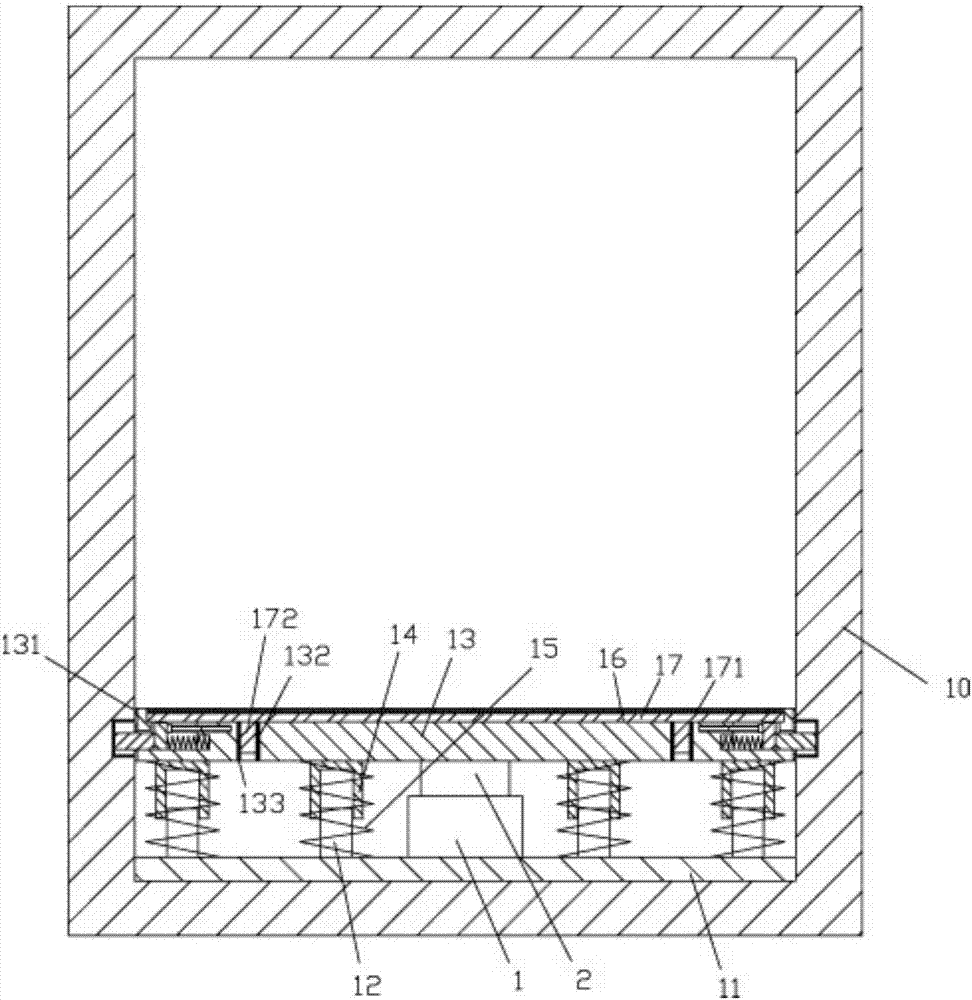
[0022] Examples, see e.g. Figure 1 to Figure 2 As shown, a buffer limit elevator car includes a car body 10, a main board body 11 is fixed on the top surface of the bottom plate of the car body 10, and a plurality of insertion rods 12 are fixed on the top surface of the main board body 11 The buffer plate 13 is located above the insertion rod 12. The bottom surface of the buffer plate 13 has a plurality of socket sleeves 14. The insertion rod 12 is inserted into the corresponding socket sleeve 14. The buffer spring 15 is inserted into the insertion rod 12 and the socket sleeve. In 14, the upper end of the buffer spring 15 focuses on the buffer plate 13, and the lower end of the buffer spring 15 focuses on the main board body 11;

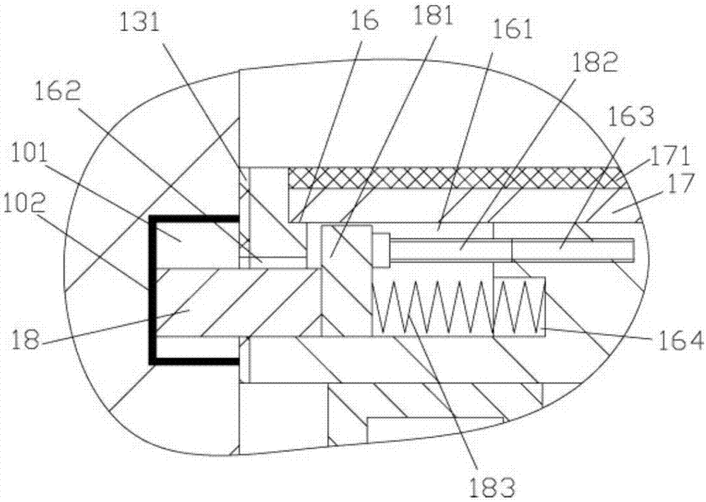
[0023] A self-lubricating layer 131 is fixed on the side wall of the buffer plate 13, and the self-lubricating layer 131 is pressed against the lower inner side wall of the car body 10;

[0024] The middle part of the top surface of the buffer plat...


PUM


Abstract

The invention discloses a buffering limiting lift car which comprises a lift car body. A main plate is fixed to the top face of a bottom plate of the lift car body. A plurality of insertion rods are fixed to the top face of the main plate. A buffer plate is located above the insertion rods, the bottom face of the buffer plate is provided with a plurality of insertion sleeves, and the insertion rods are sleeved with the insertion sleeves correspondingly. Buffer springs are inserted in the insertion rods and the insertion sleeves. The upper ends of the buffer springs act on the buffer plate, and the lower ends of the buffer springs act on the main plate. A self-lubricating layer is fixed to the side wall of the buffer plate and pressed to the lower inner side wall of the lift car body in an abutting mode. A mounting groove is formed in the middle of the top face of the buffer plate. Lower insertion grooves are formed in the bottom faces of the two sides of the mounting groove. The inner side walls of the lower insertion grooves are provided with radial through grooves which correspond to limiting grooves formed in the inner side wall of the lift car body. The buffer plate has a buffer effect, can prevent passengers from being highly impacted during vertical ascending and descending and can also prevent shaking, so that the lifting effect is improved.

Description

[0001] Technical field: [0002] The invention relates to the technical field of elevator equipment, and more specifically relates to a buffer-limited elevator car. [0003] Background technique: [0004] In the car of the existing elevator, its general bottom surface is not equipped with a buffer mechanism. The buffer generated when the elevator lifts up and down tends to make the passengers in the car feel up and down, and the riding effect is not ideal. [0005] Invention content: [0006] The purpose of the present invention is to overcome the deficiencies of the prior art and provide a buffer limit elevator car, its buffer plate has a buffer effect, which can prevent the passengers from going up and down from excessive impact and vibration, and improve the lifting effect. [0007] The scheme that the present invention solves described technical problem is: [0008] A buffer limit elevator car, including a car body, a main board body is fixed on the top surface of the bot...

Claims


Application Information

Patent Timeline
Patent Type & Authority Applications(China)
IPC IPC(8): B66B11/02F16F15/04
CPCB66B11/0266
Inventor 陈玉燕
Owner 江苏奥菱电梯有限公司
Why Eureka
Try Eureka