Locking valve

A valve and valve switch technology, applied in valve details, valve device, valve shell structure, etc., can solve problems such as affecting valve service life, causing accidents, and adverse valve protection.

Active Publication Date: 2017-09-05
名盾有限公司
View PDF4 Cites 3 Cited by
  • Summary
  • Abstract
  • Description
  • Claims
  • Application Information

AI Technical Summary

Problems solved by technology

[0002] The opening and closing parts of the valve are driven by the rotation of the valve stem to realize the adjustment and control of the fluid, and the rotation of the valve stem is controlled by the valve switch connected to it. The valve switches of traditional valves are all exposed outside the valve body. Anyone can control the rotation of the valve stem by operating the valve switch. Therefore, if the valve switch is supposed to be in the closed position, if it is opened without authorization, it will cause waste of fluid. In severe cases, it may even cause accidents. In order to solve the above problems, the valve switch will be locked by the locking device so that it cannot be rotated. The traditional locking device completes the locking function by locking the lock core in the lock hole, but due to structural limitations, the lock core and the lock hole The positions are all located outwards. Once someone deliberately destroys it, the locking device can be easily damaged, which is not conducive to the protection of the valve. Moreover, when the general locking device locks the valve, its own structure will appear upturned. Lift and squeeze the valve switch, causing damage to the valve switch and affecting the service life of the valve

Method used


Image

  • Locking valve
  • Locking valve
  • Locking valve

Examples


Embodiment 1

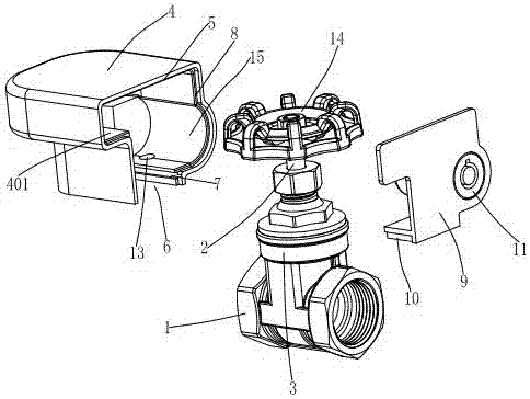
[0016] Example 1, please refer to figure 1 , figure 2 , the present invention provides a locking valve disclosed by the present invention, comprising a valve body 1, an opening and closing member disposed in the valve body 1, and a valve stem 2 connected with the opening and closing member. The valve body 1 is provided with a middle hole 3, One end of the valve stem 2 runs through the middle hole 3 and is connected with a valve switch. The valve body 1 is covered with a protective cover 4, and one side of the protective cover 4 is provided with an opening 5. One end of the valve stem 2 is located in the protective cover 4; the bottom of the protective cover 4 is provided with a U-shaped mouth 6; the two sides of the U-shaped mouth 6 are provided with mutually symmetrical slideways 7; the opening 5 is provided with a mounting Step 8; the installation step 8 is covered with a cover plate 9, and the cover plate 9 covers and closes the opening 5; the bottom of the cover plate 9 ...

Embodiment 2

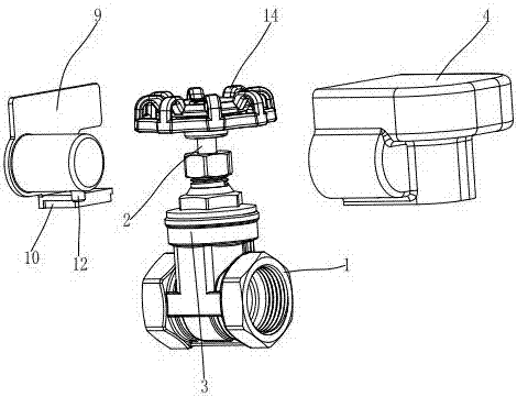
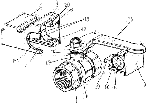
[0022] Example 2, see image 3 , Figure 4 , the present invention discloses a locking valve, comprising a valve body 1, an opening and closing member arranged in the valve body 1, and a valve stem 2 connected with the opening and closing member. The valve body 1 is provided with a middle hole 3, and the valve stem 2 One end goes through the middle hole 3 and is connected with a valve switch. The valve body 1 is covered with a protective cover 4, and one side of the protective cover 4 has an opening 5. The valve switch, the middle hole 3, and the valve stem 2 passing through the middle hole 3 One end is located in the protective cover 4; the bottom of the protective cover 4 is provided with a U-shaped mouth 6; the two sides of the U-shaped mouth 6 are provided with mutually symmetrical slideways 7; the opening 5 is provided with a mounting step 8; The installation step 8 is covered with a cover plate 9, and the cover plate 9 closes the opening 5; the bottom of the cover plate...

Embodiment 2

[0025] The usage method of embodiment two is as follows:

[0026] When the valve needs to be used, the lock body 11 can be rotated by a key so that the lock core 12 is retracted toward the lock body 11. At this time, the lock core 12 is separated from the lock hole 13, and there is no gap between the protective cover 4 and the cover plate 9. Then connect, the staff can remove the cover plate 9 from the installation step 8 of the protective cover 4 by external force, so that the cover plate 9 is separated from the protective cover 4, and after the protective cover 4 loses the restriction of the cover plate 9, the protective cover 4 can pass through. The opening 5 and the U-shaped port 6 slide out from the valve body 1 to separate from it, and then the handle 16 can be rotated according to actual needs.

[0027]When the valve needs to be protected again after the rotation of the handle 16 is completed, the staff can hold the protective cover 4 and move the opening 5 of the prote...


PUM


Abstract

A locking valve comprises a valve body, an opening and closing member arranged in the valve body and a valve stem connected with the opening and closing member. A middle hole is formed in the valve body, one end of the valve stem penetrates out of the middle hole and is connected with a valve switch, the valve body is covered with a protective cover, an opening is formed in one side of the protective cover, and the valve switch, the middle hole and the valve stem penetrating out of the middle hole are all located in the protective cover. A U-shaped opening is formed in the bottom of the protective cover. Symmetrical sliding ways are arranged on the two sides of the U-shaped opening. A mounting step is arranged on the opening. The mounting step is covered with a cover plate. The opening is covered and closed with the cover plate. A sliding seat matched with the sliding ways is arranged at the bottom of the cover plate. By the adoption of the locking valve, when the valve switch is locked, a lock cylinder and a lock hole can be hidden, damage to the lock cylinder and the lock hole by strangers is avoided, extrusion and damage to the valve switch is avoided in the valve switch locking process, and the service life of the valve is guaranteed.

Description

technical field [0001] The invention relates to a lock valve. Background technique [0002] The opening and closing parts of the valve are driven by the rotation of the valve stem to realize the adjustment and control of the fluid, and the rotation of the valve stem is controlled by the valve switch connected to it. The valve switches of traditional valves are all exposed outside the valve body. Anyone can control the rotation of the valve stem by operating the valve switch. Therefore, if the valve switch is supposed to be in the closed position, if it is opened without authorization, it will cause waste of fluid. In severe cases, it may even cause accidents. In order to solve the above problems, the valve switch will be locked by the locking device so that it cannot be rotated. The traditional locking device completes the locking function by locking the lock core in the lock hole, but due to structural limitations, the lock core and the lock hole The positions are all loca...

Claims


Application Information

Patent Timeline
Patent Type & Authority Applications(China)
IPC IPC(8): F16K27/12F16K35/06F16K31/60
CPCF16K27/12F16K31/60F16K35/06
Inventor 陶礼福
Owner 名盾有限公司
Why Eureka
Try Eureka