Supercharge Your Innovation With Domain-Expert AI Agents!

Ballast tank water taking device and applications thereof

A water intake device and ballast tank technology, applied in the field of ships, can solve problems such as difficulty in opening the cover to take water, and the inability to open the cover for sampling, etc., and achieve the effects of saving manpower and material resources, preventing water leakage, and simplifying the operation of water intake.

Inactive Publication Date: 2017-09-05
GUANGZHOU SHIPYARD INTERNATIONAL LTD
View PDF5 Cites 3 Cited by
  • Summary
  • Abstract
  • Description
  • Claims
  • Application Information

AI Technical Summary

Problems solved by technology

When the deck surface of a conventional oil tanker or bulk carrier is used as the top wall of the ballast tank, the staff can open the cover for ballast water sampling on the deck surface, but cannot open the cover for the ballast tank not close to the deck surface It i

Method used


Image

  • Ballast tank water taking device and applications thereof
  • Ballast tank water taking device and applications thereof
  • Ballast tank water taking device and applications thereof

Examples


Embodiment 1

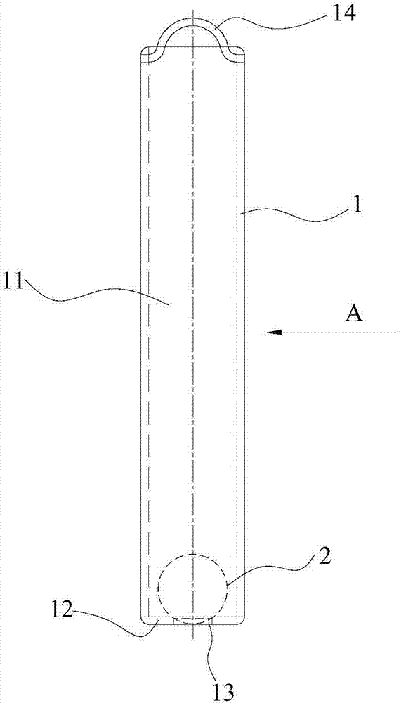
[0039] Such as figure 1 As shown, the ballast tank water intake device in this embodiment includes: a water intake device body 1, which has a hollow structure housing chamber 11 inside, and is provided with the housing chamber 1 on the water intake device body 1. 11 is connected to the water inlet hole 13; the blocking member 2, the blocking member 2 is arranged in the accommodating chamber 11, and is used to selectively block the water inlet hole 13: when the accommodating chamber 11 needs to enter When there is water, the water inlet hole 13 is opened, and the accommodating chamber 11 communicates with the outside through the water inlet hole 13. When the accommodating chamber 11 is full of water, the blocking member 2 blocks the water hole13.

[0040] Wherein, the water intake device body 1 is made of stainless steel pipe.

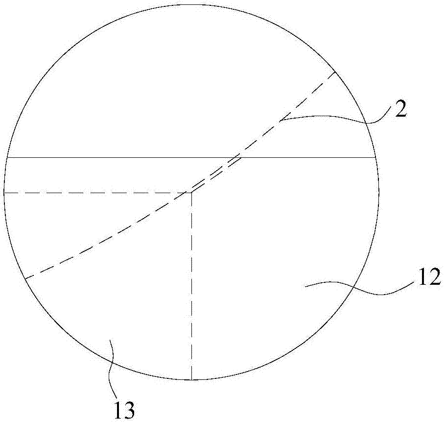
[0041] In this embodiment, a water intake hole 13 is provided on the water intake device body 1, and a blocking member 2 for selectively blocking the...

Embodiment 2

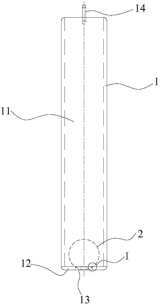
[0054] The part of the ballast tank water intake device in this embodiment follows the reference numerals in the first embodiment.

[0055] In this embodiment, the water intake device for the ballast tank includes: a water intake device body 1 having a hollow housing cavity 11 inside the water intake device body 1, and a hole communicating with the housing cavity 11 is opened on the water intake device body 1 The water inlet hole 13; the blocking member 2, the blocking member 2 is arranged in the accommodating chamber 11 to selectively block the water inlet hole 13: when the accommodating chamber 11 needs to enter water, The water inlet hole 13 is opened, and the accommodating chamber 11 communicates with the outside through the water inlet hole 13. When the accommodating chamber 11 is full of water, the blocking member 2 blocks the water inlet hole 13 .

[0056] In this embodiment, a water intake hole 13 is provided on the water intake device body 1, and a blocking member 2 ...


PUM

PropertyMeasurementUnit
Densityaaaaaaaaaa
Densityaaaaaaaaaa

Abstract

The invention discloses a ballast tank water taking device. The ballast tank water taking device comprises a water taking device body; a hollow accommodation cavity is arranged in the water taking device body; and a water inlet that is communicated with the accommodation cavity is arranged in the water taking device body. The ballast tank water taking device also comprises a blocking member, which is arranged in the accommodation cavity and is used to selectively block the water inlet. When the accommodation cavity needs water, the water inlet is opened, the accommodation cavity is communicated with the exterior through the water inlet, and when the accommodation cavity is full of water, the blocking member blocks the water inlet. When the ballast tank water taking device is soaked in water, water enters the accommodation cavity of the ballast tank water taking device through the water inlet arranged in the water taking device body, and when the accommodation cavity is full of water, the blocking member in the accommodation cavity can block the water inlet to prevent water leakage. The water taking operation of the ballast tank water taking device is very simple, people do not need to open a ballast tank and enter the ballast tank to take water, the danger of water taking operation is reduced, and compared with a conventional water taking method, human and material resources are saved.

Description

technical field [0001] The invention relates to the technical field of ships, in particular to a ballast tank water intake device and its application. Background technique [0002] In existing ships, when performing inclination tests or conventional ballast water sampling, it is necessary to open the deck to take water. When the deck surface of a conventional oil tanker or bulk carrier is used as the top wall of the ballast tank, the staff can open the cover for ballast water sampling on the deck surface, but cannot open the cover for the ballast tank not close to the deck surface It is very difficult to take water or open the cover to take water; the ballast tanks of semi-submersible ships are multi-storey ships, and there are no personnel access hatches on the top of the middle and bottom ballast tanks, so it is impossible to open the cover for sampling. Contents of the invention [0003] One object of the present invention is to provide a ballast tank water intake devi...

Claims


Application Information

Patent Timeline
IPC IPC(8): G01N1/10
CPCG01N1/10G01N2001/1031
Inventor 程超
Owner GUANGZHOU SHIPYARD INTERNATIONAL LTD
Features
  • R&D
  • Intellectual Property
  • Life Sciences
  • Materials
  • Tech Scout
  • Unparalleled Data Quality
  • Higher Quality Content
  • 60% Fewer Hallucinations
Learn More