LED (light emitting diode) display
A technology of LED display screen and LED module, which is applied to the casing with display/control unit, identification device, electrical equipment casing/cabinet/drawer, etc., can solve the problem of long disassembly time, errors, disassembly and maintenance Time and other issues, to achieve the effect of short disassembly time and convenient maintenance
- Summary
- Abstract
- Description
- Claims
- Application Information
AI Technical Summary
Problems solved by technology
Method used
Image
Examples
Embodiment 1
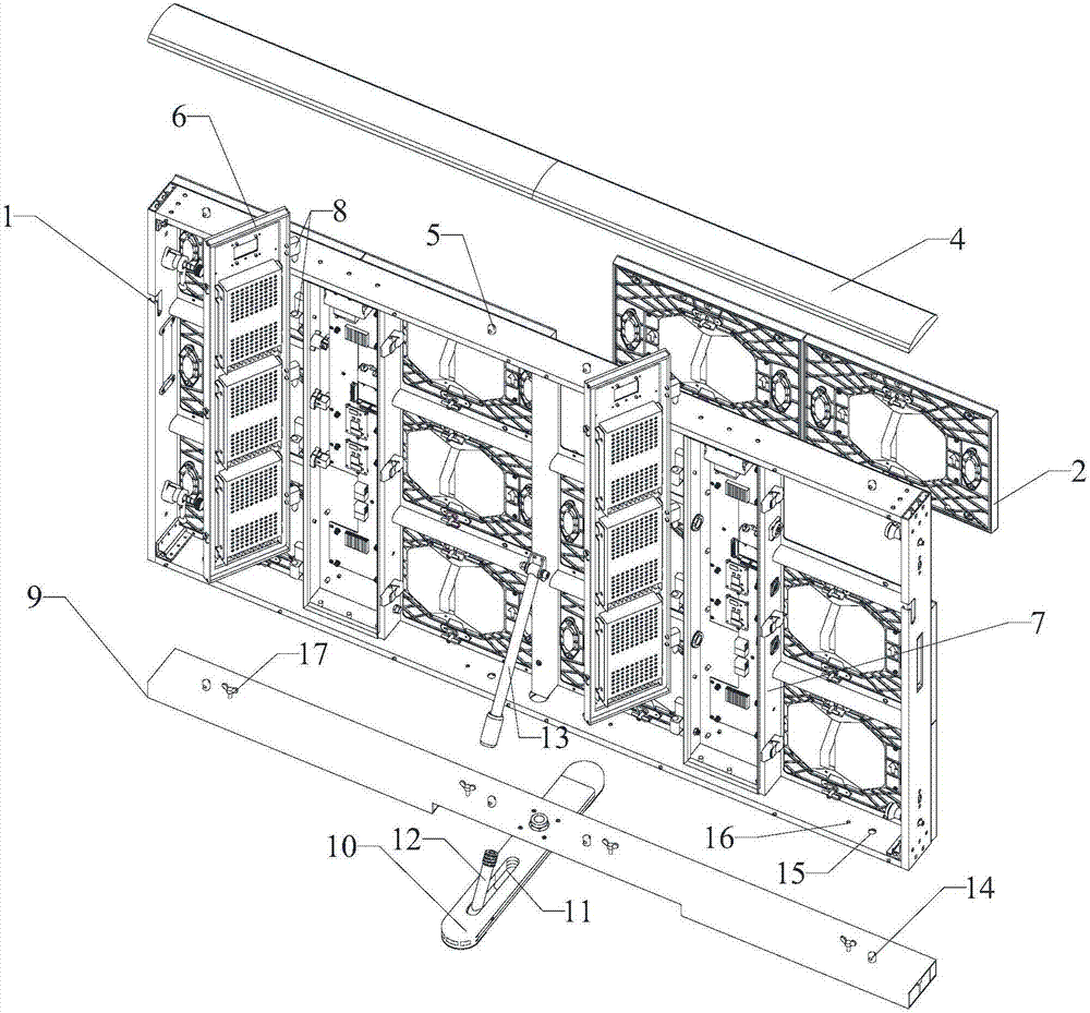
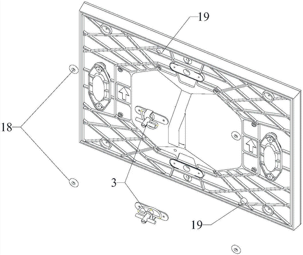
[0064] Please refer to Figure 1 to Figure 5 , an LED display screen, including a box frame 1 and an LED module 2, the box frame 1 can be such as figure 1 As shown in the grid shape, one LED module 2 can be set in each grid; it also includes a knob 3, which is fixed on the reverse side of the LED module 2; when the knob 3 is tightened, it contacts the box frame 1 to realize the box The fixed connection between the body frame 1 and the LED module 2;
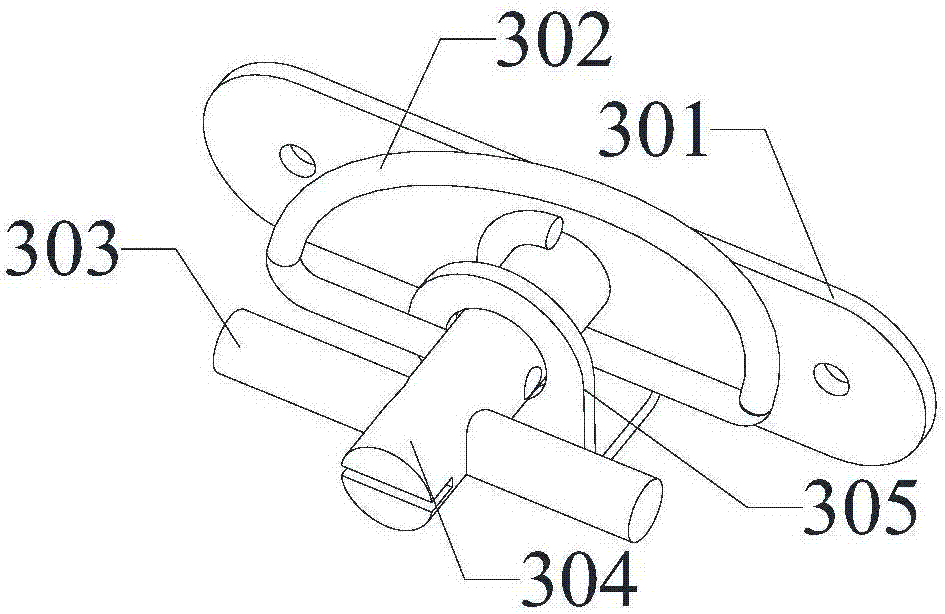
[0065] The knob 3 includes a mounting plate 301 , a lock cylinder 304 , a handle 303 and a spring wire core 302 ; the middle part of the mounting plate 301 is provided with an extension 305 extending upward perpendicular to the mounting plate 301 , and the end of the extension 305 is bent and opposite to the mounting plate 301 , the extension part 305 may be in an "L" shape;
[0066]The lock core 304 is fixed on the LED module 2 through the mounting plate 301, a small hole can be set on the left and right sides of the mounting p...
Embodiment 2
[0076] Please refer to figure 1 , an LED display screen, comprising a box frame 1, an LED module 2, a system control box 7, a power drive rear cover 6, a support base and a protective cover 4;
[0077] The box frame 1 is spliced by profiles, the bottom of the box frame 1 is provided with a second positioning hole 15 and a through hole 16, the top of the box frame 1 is provided with a third positioning column 5, and the back of the box frame 1 is provided with a movable The first connector 13 can be provided with the number and position of the second positioning hole 15, the through hole 16, and the third positioning column 5 according to the needs of the actual situation;
[0078] The reverse side of the LED module 2 is provided with a knob 3, which contacts the box frame 1 when the knob 3 is tightened, so as to realize the fixed connection between the box frame 1 and the LED module 2;
[0079] The system control box 7 is fixed on the box frame 1, and the system control box...
Embodiment 3
[0090] Please refer to Figure 1 to Figure 7 , an LED display screen, comprising a box frame 1, an LED module 2, a system control box 7, a power drive rear cover 6, a support base and a protective cover 4;
[0091] The box frame 1 is spliced by profiles, the bottom of the box frame 1 is provided with a second positioning hole 15 and a through hole 16, the top of the box frame 1 is provided with a third positioning column 5, and the back of the box frame 1 is provided with a movable The first connector 13, the front of the box frame 1 is provided with a suction cup 20 and a first positioning hole 21;
[0092] The reverse side of the LED module 2 is provided with a knob 3, a magnet 18, and a first positioning column 19. When the knob 3 is tightened, it contacts the box frame 1 to realize the fixed connection between the box frame 1 and the LED module 2. The magnet 18 and the suction cup 20 suction connection, the first positioning column 19 is matched with the first positioni...
PUM
 Abstract
Description
Claims
Application Information
 - R&D
- Intellectual Property
- Life Sciences
- Materials
- Tech Scout
- Unparalleled Data Quality
- Higher Quality Content
- 60% Fewer Hallucinations
Browse by: Latest US Patents, China's latest patents, Technical Efficacy Thesaurus, Application Domain, Technology Topic, Popular Technical Reports.
© 2025 PatSnap. All rights reserved.Legal|Privacy policy|Modern Slavery Act Transparency Statement|Sitemap|About US| Contact US: help@patsnap.com


