
Limit switch core structure

A limit switch and core technology, applied in the field of limit switch core structure, can solve the problems of large switch action parameters, signal flicker or power failure, switch accuracy and action parameter tolerance changes, etc., to achieve convenient external wiring, The effect of high assembly efficiency

Active Publication Date: 2019-08-02
ZHANGZHOU JUANMEI ELECTRIC TECH CO LTD
View PDF5 Cites 0 Cited by
  • Summary
  • Abstract
  • Description
  • Claims
  • Application Information

AI Technical Summary

Problems solved by technology

[0003] Purpose of the invention: The present invention provides a limit switch core structure, in order to solve the problems of signal flickering or power failure, large switch action parameters, large switch accuracy and action parameter tolerance changes in long-term switch applications

Method used


Image

  • Limit switch core structure
  • Limit switch core structure
  • Limit switch core structure

Examples


Embodiment Construction

[0027] The present invention will be further described below in conjunction with the accompanying drawings.

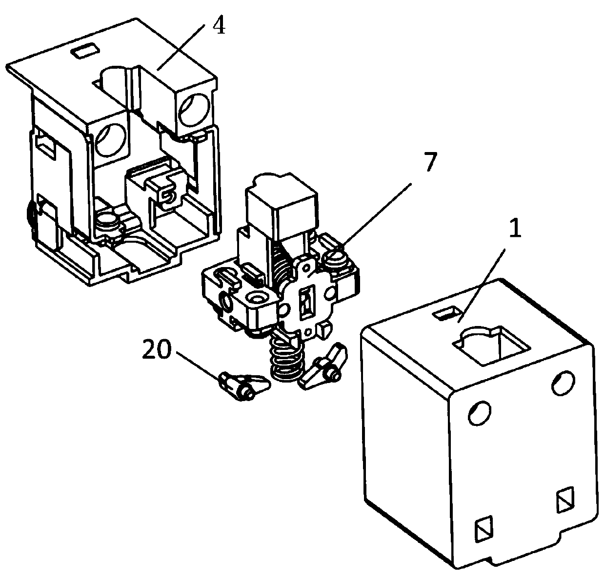
[0028] Such as figure 1 - As shown in -8, a switch core structure, which includes: a bottom shell 1, the bottom of which is provided with a positioning boss 2, groove guide rails 3 are arranged on both sides of the positioning boss 2, and the surface of the positioning boss 2 is a folded surface;

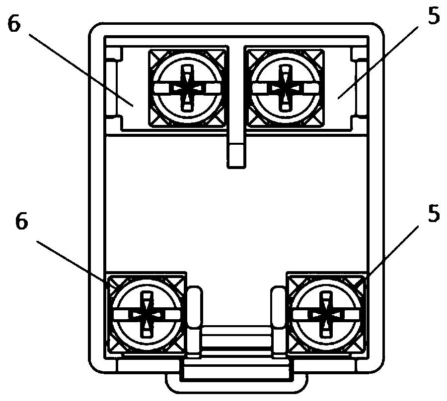
[0029] The base assembly 4 is assembled in the bottom case 1. The base assembly 4 includes a static contact base 18. One side of the base assembly 4 is provided with an opening, and the other side is provided with normally open and normally closed connector assemblies. The open connector assembly 5 and the normally closed connector assembly 6 include a static contact piece connector 16 and a static contact piece fixing piece 17 respectively, and the static contact piece connector 16 is fixed on the static contact piece base 18 in an embedded manner. The embedded fixing meth...


PUM


Abstract

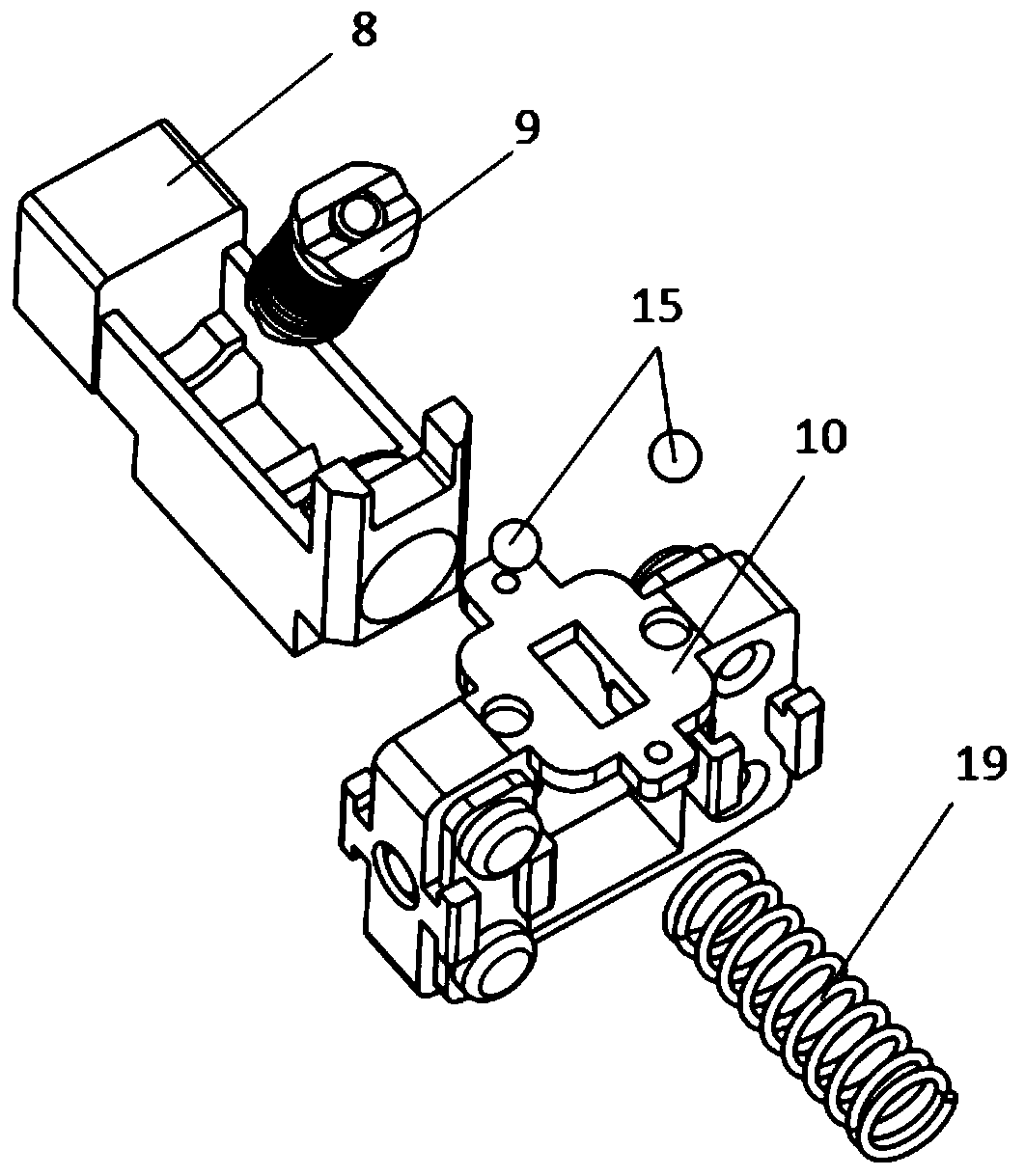
The invention discloses a core structure of a limit switch. The core structure comprises a bottom casing, a pedestal assembly and a movable assembly; the bottom of the bottom casing is provided with a positioning boss, the two sides of the positioning boss are provided with grooved guide rails respectively, and the surface of the positioning boss is a folding surface; the pedestal assembly is assembled in the bottom casing; the movable assembly is assembled in the pedestal assembly, and comprises a movable rod, an elastic assembly and a moving contact assembly, the elastic assembly comprises main springs, auxiliary springs and a telescopic rod, the auxiliary springs can drive the telescopic rod to be telescopic along the axial direction, the moving contact assembly comprises a moving contact pedestal, and the moving contact pedestal is provided with a through hole through which the telescopic rod can penetrate freely and countersinks for accommodating rolling bodies; and the rolling bodies can move along the grooved guide rails, and the telescopic rod can bear a force to penetrate the moving contact pedestal and make contact with an inclined plane of the positioning boss. The core structure can prevent the switch from a power-off or flickering phenomenon in the switching moment effectively, a sliding body reduce the frictional force generated during movement of the movable assembly, the positions and quantity of normally-open and normally-closed socket connectors can be changed more conveniently, and the switching manner and repetition precision are improved.

Description

technical field [0001] The invention relates to a switch, in particular to a limit switch core structure. Background technique [0002] Most of the existing limit switch cores are in the form of springs or shrapnel. When the switch moving contact piece changes from normally closed contact to normally open contact, it is prone to non-conduction or signal flickering. This phenomenon is likely to cause malfunction of machinery and equipment. If the machine is damaged, it may cause the elevator to stop or start unexpectedly when used on the elevator, and the door cannot be opened when used on the train, and passengers need to evacuate urgently. At present, the solution to this problem is mostly to make the metal movable contact piece movable and add a small spring to position it on the plastic bracket. The action force of the large spring is much greater than the force of the small spring to alleviate this problem. This method brings The problem is that the action parameters of...

Claims


Application Information

Patent Timeline
Patent Type & Authority Patents(China)
IPC IPC(8): H01H3/16H01H3/32H01H3/38H01H1/50H01H1/58
CPCH01H1/50H01H1/58H01H3/16H01H3/32H01H3/38
Inventor 戴四川
Owner ZHANGZHOU JUANMEI ELECTRIC TECH CO LTD
Learn More