Array substrate, preparation method thereof and display panel

A technology for array substrates and display panels, which is applied in the fields of semiconductor/solid-state device manufacturing, semiconductor/solid-state device components, instruments, etc., and can solve the problems that the related processes of array substrates need to be improved.

Inactive Publication Date: 2017-09-05
BOE TECH GRP CO LTD +1
View PDF3 Cites 4 Cited by
  • Summary
  • Abstract
  • Description
  • Claims
  • Application Information

AI Technical Summary

Problems solved by technology

[0003] Therefore, the current array substrate-related processes still need to be improved

Method used


Image

  • Array substrate, preparation method thereof and display panel
  • Array substrate, preparation method thereof and display panel
  • Array substrate, preparation method thereof and display panel

Examples


Embodiment Construction

[0085] The embodiments of the present invention are described in detail below, and those skilled in the art will understand that the following embodiments are intended to explain the present invention, and should not be regarded as limiting the present invention. Unless otherwise specified, in the following examples that do not explicitly describe specific techniques or conditions, those skilled in the art can carry out according to commonly used techniques or conditions in this field or according to product instructions. The reagents or instruments used were not indicated by the manufacturer, and they were all commercially available conventional products.

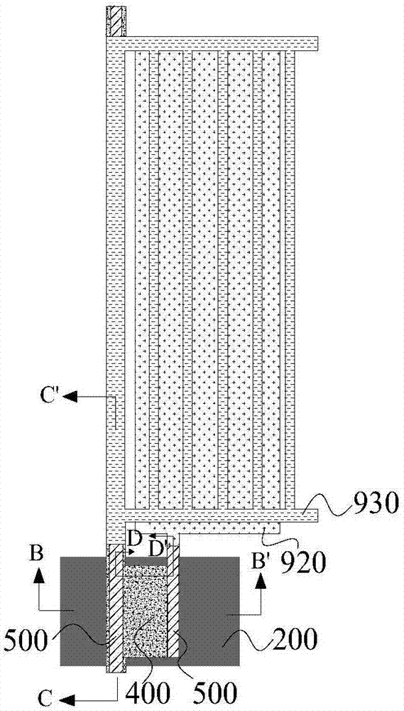
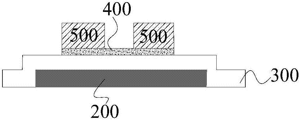
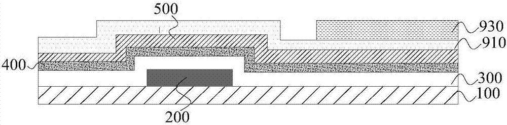
[0086] In one aspect of the present invention, the present invention provides an array substrate. refer to Figure 3a-8d , to describe the array substrate of the present invention in detail.

[0087] According to an embodiment of the present invention, the array substrate includes: a base substrate 100, a thin film trans...


PUM


Abstract

The invention provides an array substrate, a preparation method thereof and a display panel. The array substrate comprises a substrate base plate, a thin film transistor arranged on one side of the substrate base plate, a data line arranged on one side of the substrate base plate, and a connecting electrode making a source and a drain of the thin film transistor electrically connected with the data line, wherein the orthographic projection of an active layer of the thin film transistor on the substrate base plate is located in the orthographic projection of a grid of the thin film transistor on the substrate base plate. The projection of the active layer of the array substrate on a grid insulation layer is located in the projection of the grid on the grid insulation layer, the source and the drain are connected with the data line through the connecting electrode, and therefore the light electric leakage problem caused when the active layer is exposed out of the grid is reduced, and the display stability of the display panel formed by the array substrate is improved.

Description

technical field [0001] The present invention relates to the field of display technology, in particular, the present invention relates to an array substrate, a preparation method thereof, and a display panel. Background technique [0002] In the current pixel design, in order to save costs, the scheme of reducing the number of masks (MASK) is generally adopted, that is, the source-drain electrode layer (SD) and the active layer (ACT) share a half-tone mask (HTM MASK) scheme, and this scheme has been used on many pixel designs. However, there will be ACT under the SD metal formed by HTM NASK, refer to Figure 1a ~ Figure 1d and figure 2 ,especially in figure 2 In the three channels shown (I, II, III), the active layer (Active) at the source and drain electrodes will leak out of the gate (gate). When illuminated (hv), refer to figure 2 , the characteristics of the active layer 400 outside the gate 200 will change, the holes at the source 500 will increase with the light,...

Claims


Application Information

Patent Timeline
Patent Type & Authority Applications(China)
IPC IPC(8): H01L27/12H01L23/552H01L21/77
CPCH01L23/552H01L27/1214H01L27/124H01L27/1259G02F1/1368G02F1/136286H01L27/1222H01L27/127
Inventor 臧鹏程高山徐元杰
Owner BOE TECH GRP CO LTD
Why Eureka
Try Eureka