Driving device and data output method

A driving device and data technology, applied in the direction of instruments, static indicators, etc., can solve the problems of chromatic aberration recognizable by human eyes, reducing the display stability of AMOLED display panels, and affecting the accuracy of AMOLED display panels, etc.

Active Publication Date: 2017-05-31
芯颖科技有限公司
View PDF6 Cites 2 Cited by
  • Summary
  • Abstract
  • Description
  • Claims
  • Application Information

AI Technical Summary

Problems solved by technology

However, due to the continuous change of the voltage applied across the capacitor to the continuous charging and discharging process of the capacitor, it will continuously generate instantaneous peak current
However, in the AMOLED display panel, the loading voltage at both ends of multiple capacitors changes, and the total instantaneous peak current formed by the multiple instantaneous peak currents generated by it can cause a large instantaneous voltage dr

Method used


Image

  • Driving device and data output method
  • Driving device and data output method
  • Driving device and data output method

Examples


no. 1 example

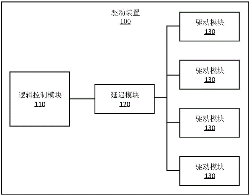
[0031] see figure 1 , The first embodiment of the present invention provides a driving device 100 , the driving device 100 includes: a logic control module 110 , a delay module 120 and multiple groups of driving modules 130 .

[0032] The logic control module 110 is used to generate multiple sets of corresponding voltage selection data according to a preset program or a control instruction input by a user. Then output the multiple sets of voltage selection data generated to the delay module 120 .

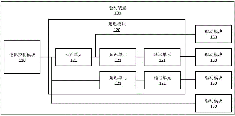
[0033] The delay module 120 is used to delay and output each set of obtained voltage selection data to the corresponding driving module 130 according to different preset delay time lengths, so as to reduce the peak signal superposition generated by each group of driving modules 130 according to the corresponding voltage selection data The resulting total peak signal. Wherein, the delay module 120 has multiple delay circuits inside, and the delay of each delay circuit can always be...

no. 2 example

[0047] see Figure 5 with Figure 6 , the second embodiment of the present invention provides a driving device 100 , and the driving device 100 also includes: a logic control module 110 , a delay module 120 and multiple groups of driving modules 130 . Compared with the first embodiment, the difference is that the output end of each driving module 130 is coupled to the logic control module 110 , and each group of driving devices 100 is provided with a switch S.

[0048] The logic control module 110 can also generate four sets of voltage selection data according to a preset program or a control command input by a user, and output each set of voltage selection data to the corresponding driving module 130 . In addition, the logic control module 110 can also generate four sets of switch control signals according to a preset program or a control instruction obtained from a user, and output each set of switch control signals to the delay module 120 .

[0049] The delay module 120 a...


PUM


Abstract

An embodiment of the invention belongs to the technical field of AMOLED (active-matrix organic light emitting diode) and provides a driving device and a data output method. The driving device is applied to an AMOLED display panel and comprises a logic control module, a delay module and multiple groups of driving modules. An input end of the delay module is coupled with an output end of the logic control module, input ends of each group of the driving modules are coupled with an output end of the delay module, and each group of the driving modules are used for being coupled with an external power source. A plurality of groups of voltage selection data are generated and outputted through the logic control module and outputted to the corresponding driving modules in a delayed manner respectively by the delay module according to different preset delay durations, and accordingly total peak signals are greatly reduced, and display stability of the AMOLED display panel is effectively improved.

Description

technical field [0001] The present invention relates to the technical field of AMOLED display panels, in particular to a driving device and a data output method. Background technique [0002] With the continuous development and improvement of science and technology, active-matrix organic light emitting diodes (AMOLED, Active-matrix organic light emitting diode) have been widely used in the display technology of mobile phones. [0003] In the prior art, if different voltages are applied to both ends of each capacitor in the AMOLED display panel, the organic light-emitting diode (UIV OLED) display corresponding to the capacitor will be different. Therefore, by continuously changing the voltage value loaded on both ends of each capacitor in the AMOLED display panel, the display picture on the AMOLED display panel can be changed. However, due to the continuous change of the applied voltage at both ends of the capacitor is the process of continuous charging and discharging of th...

Claims


Application Information

Patent Timeline
IPC IPC(8): G09G3/3225
CPCG09G3/3225
Inventor 崔佳男吴常谦王非
Owner 芯颖科技有限公司
Why Eureka
Try Eureka