
Intelligent plasma cutting machine

A plasma cutting machine and cutting head technology, applied in plasma welding equipment, welding equipment, metal processing equipment, etc., can solve problems such as inconvenient maintenance, increased labor intensity, and easy corrosion, so as to avoid the impact of production efficiency and reduce The effect of labor intensity

Active Publication Date: 2017-09-08
青岛鼎盛源钢结构有限公司
View PDF7 Cites 1 Cited by
  • Summary
  • Abstract
  • Description
  • Claims
  • Application Information

AI Technical Summary

Problems solved by technology

[0003] At present, the cutting head of the existing plasma cutting machine is mostly fixed on the cutting bridge. When the cutting head breaks down and needs to be repaired, it is very inconvenient to repair it directly on the cutting machine. At this time, it needs to be disassembled first. Many parts need to be manually disassembled during disassembly, which not only takes time and effort, increases labor intensity, but also indirectly affects production efficiency; in addition, in order to facilitate the movement and cutting of the cutting head, most of the cutting bridges are set on slide rails, and slide rails are generally It is exposed to the air, and it is easy to be corroded for a long time, which will affect the normal sliding of the cutting bridge

Method used


Image

  • Intelligent plasma cutting machine
  • Intelligent plasma cutting machine
  • Intelligent plasma cutting machine

Examples


Embodiment Construction

[0026] The present invention is described in further detail now in conjunction with accompanying drawing. These drawings are all simplified schematic diagrams, which only illustrate the basic structure of the present invention in a schematic manner, so they only show the configurations related to the present invention.

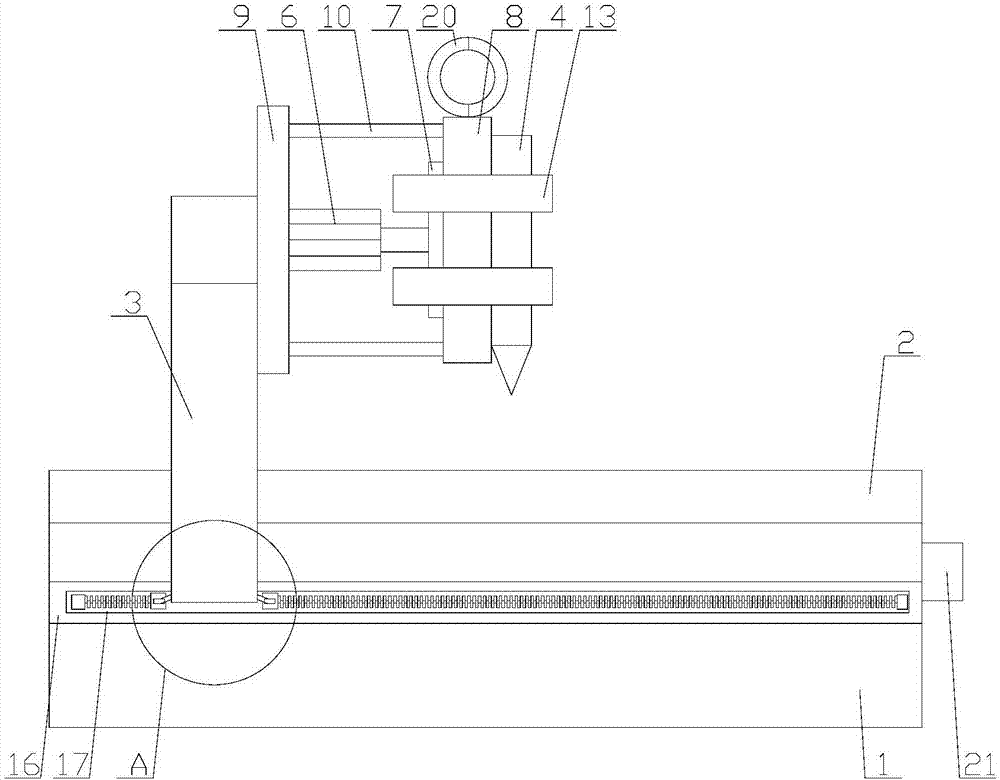
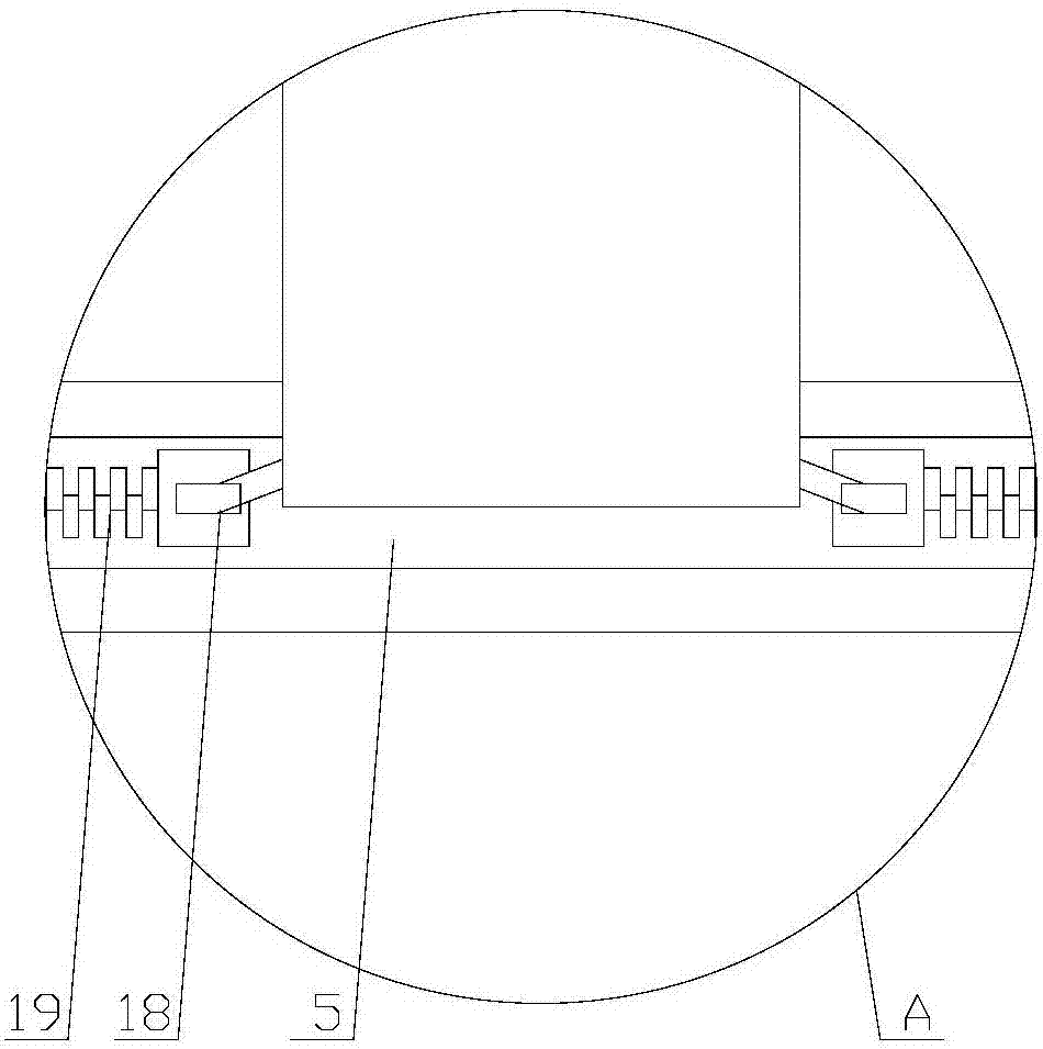
[0027] Such as Figure 1-5 As shown, a kind of intelligent plasma cutting machine comprises base 1, cutting table 2, cutting bridge 3 and cutting head 4, and described cutting bridge 3 also comprises clamping mechanism, and described clamping mechanism is arranged on cutting bridge 3 and cutting Between the heads 4, the base 1 also includes a sealing mechanism, the base 1 is provided with a slide rail 5, the bottom of the cutting bridge 3 is slidingly connected with the slide rail 5, and the sealing mechanism is arranged on the slide rail 5;

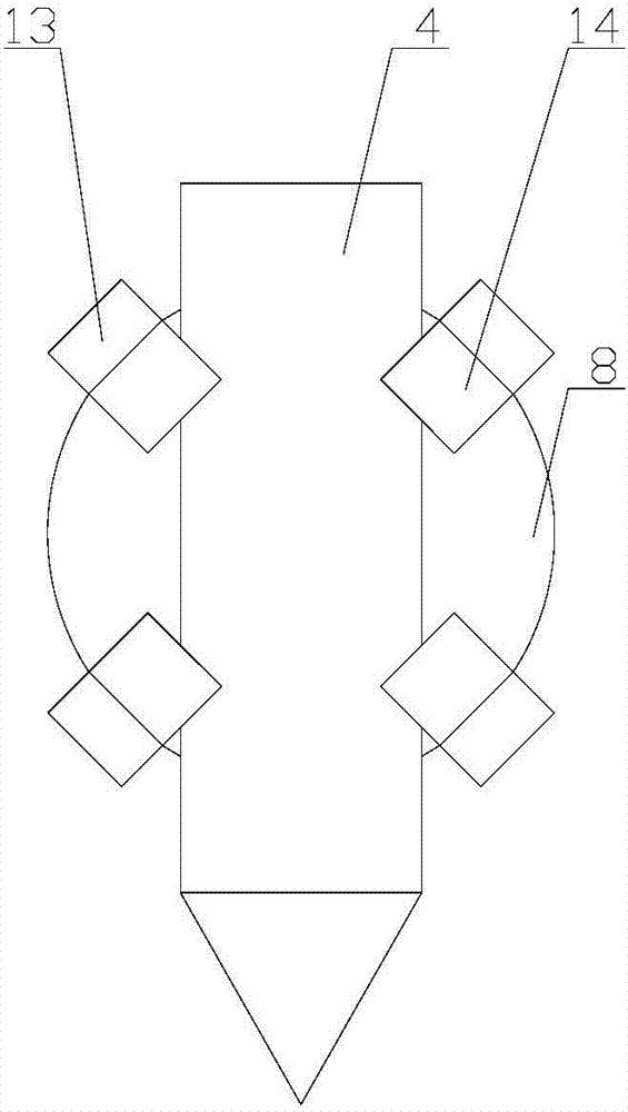
[0028] The clamping mechanism includes a driving motor 6, a driving plate 7, a fixed plate 8 and a clamping assembly,...


PUM


Abstract

The invention relates to an intelligent plasma cutting machine. The intelligent plasma cutting machine comprises a base, a cutting table, a cutting bridge and a cutting head; the cutting bridge further comprises a clamping mechanism; the base further comprises a sealing mechanism; the clamping mechanism comprises a driving motor, a driving plate, a fixing plate and a clamping assembly; the clamping assembly comprises a plurality of clamping units; the clamping units comprise driving blocks, connecting blocks and clamping blocks; and the sealing mechanism comprises a sealing cover, a chain belt and pulling heads. According to the intelligent plasma cutting machine, the clamping mechanism is arranged on the cutting bridge, when the cutting machine works normally, the clamping mechanism can clamp and fix the cutting head, when the cutting head needs to be replaced and maintained, the cutting head can be taken down from the clamping mechanism, disassembly is not needed, and therefore time and labor can be saved, the labor intensity can be relieved, and the influence on the production efficiency can also be avoided; and in addition, a sliding rail is sealed and protected through the sealing mechanism so that the phenomenon that the sliding rail is corroded due to long-term exposure to air can be avoided, and therefore normal sliding of the cutting bridge can be guaranteed.

Description

technical field [0001] The invention relates to the field of cutting equipment, in particular to an intelligent plasma cutting machine. Background technique [0002] Plasma cutting is a processing method that uses the heat of the high-temperature plasma arc to partially or partially melt (and evaporate) the metal at the incision of the workpiece, and uses the momentum of the high-speed plasma to remove the molten metal to form a cut. The plasma cutting machine is a machine that uses this method to process metal materials. [0003] At present, the cutting head of the existing plasma cutting machine is mostly fixed on the cutting bridge. When the cutting head breaks down and needs to be repaired, it is very inconvenient to repair it directly on the cutting machine. At this time, it needs to be disassembled first. Many parts need to be manually disassembled during disassembly, which not only takes time and effort, increases labor intensity, but also indirectly affects producti...

Claims


Application Information

Patent Timeline
Patent Type & Authority Applications(China)
IPC IPC(8): B23K10/00
CPCB23K10/00
Inventor 施淑琴
Owner 青岛鼎盛源钢结构有限公司
Learn More