Door hinge structure with door gap adjustment function

A gap adjustment, door hinge technology, applied in door/window fittings, building structures, suspension devices of wings, etc., can solve the problems of insecurity, falling off, affecting the use of the door body, etc., to achieve a small space, firmly linked Effect

Active Publication Date: 2018-06-19
ZHONGSHAN XIWEI KITCHEN EQUIP MFG
View PDF6 Cites 0 Cited by
  • Summary
  • Abstract
  • Description
  • Claims
  • Application Information

AI Technical Summary

Problems solved by technology

[0002] The current door structure generally adopts a rotary door opening, that is, the door body rotates around the axis of the door. In this way, the space required for opening the door is at least the rotation space with the width of the door body as the radius, and the required opening space is large, which is not convenient due to space constraints. To open the door, especially when installing large and heavy wardrobe doors, it is found that the pull-open revolving door cannot be installed in a small space, and a translational door opening method is required. The existing translational doors are hanging sliding doors, hanging sliding doors The structure determines that it cannot bear the oversized and overweight door panels for a long time, otherwise it will be deformed and fall off, which is very unsafe; in addition, the current door body will produce errors during the installation process, and the bottom side of the door body will be sealed with the bottom side. There is a large gap at the place, or there is a large gap at the side of the door body and the side seal, which affects the appearance and use of the door after the door is installed, especially for the two doors that are set opposite to each other. Larger gaps completely affect the use of the entire door body

Method used


Image

  • Door hinge structure with door gap adjustment function
  • Door hinge structure with door gap adjustment function
  • Door hinge structure with door gap adjustment function

Examples


Embodiment Construction

[0026] The technical solutions in the embodiments of the present invention are clearly and completely described below in conjunction with the drawings in the embodiments of the present invention. It should be understood that the specific embodiments described here are only used to explain the present invention, and do not limit the protection scope of the present invention.

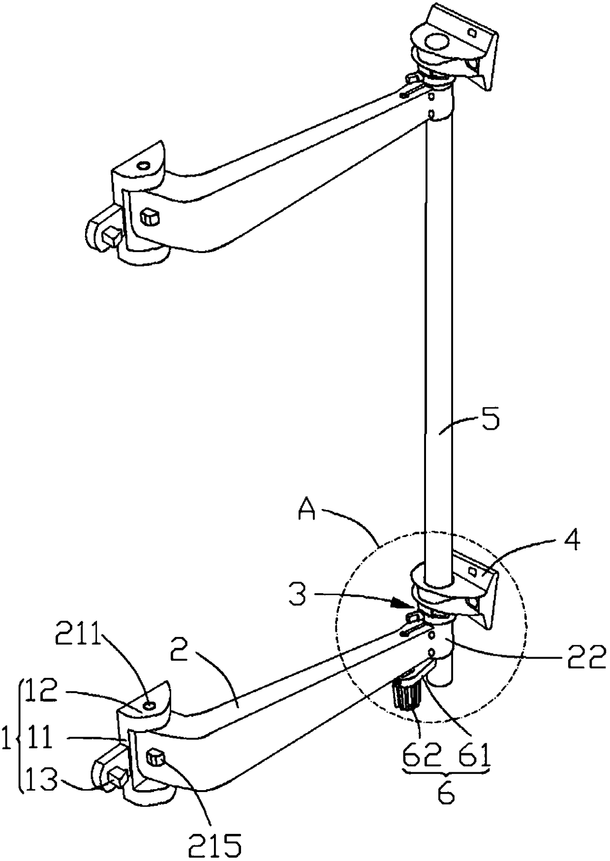
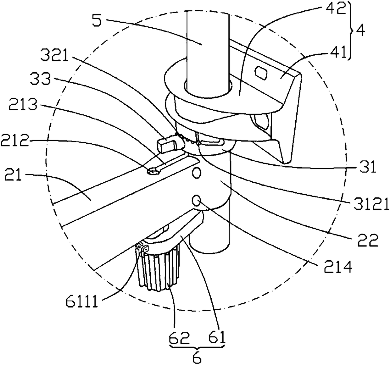
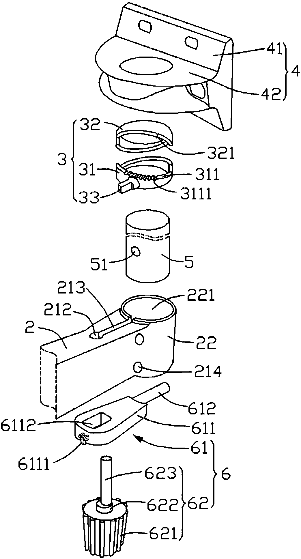
[0027] see figure 1 and figure 2 , the present invention provides a door hinge structure with the function of adjusting the gap between the doors, including a hinge seat 1, a rotating arm 2, a height adjustment member 3, a fixed seat 4, a rotating shaft 5 and a width adjustment member 6, and the hinge seat 1 is fixed on the box On the wall or the wall, the fixed seat 4 is fixed on the door body, the rotating shaft 5 is rotatably sleeved on the fixed seat 4, one end of the rotating arm 2 is rotatably connected to the hinge seat 1, and the other end is rotatably connected to the rotating shaft 5 There is...


PUM


Abstract

The invention provides a door hinge structure with a door slot gap adjusting function. The door hinge structure comprises a hinge seat, a rotary arm, a height adjusting piece, a fixed seat, a rotary shaft and a width adjusting piece. The hinge seat is fixedly connected to a box wall or a wall. The fixed seat is fixed to a door body. The rotary shaft is rotationally arranged on the fixed seat in a sleeving mode. One end of the rotary arm is rotationally connected to the hinge seat, and the other end of the rotary arm is rotationally connected to the rotary shaft. The rotary shaft is sleeved with the height adjusting piece, the bottom end of the height adjusting piece abuts against the end, connected with the rotary shaft, of the rotary arm, and the top end of the height adjusting piece abuts against the fixed seat and is used for ascending and descending relative to the rotary arm by abutting against the fixed seat. The width adjusting piece comprises a horizontal connecting piece and an eccentric rotating piece. One end of the horizontal connecting piece is fixedly connected to the rotary shaft, and the other end of the horizontal connecting piece is provided with a cam hole. The eccentric rotating piece comprises an eccentric wheel and a positioning shaft. The eccentric wheel of the eccentric rotating piece is inserted into the cam hole, the positioning shaft is inserted into the rotary arm, and motion of the positioning shaft in the horizontal direction is limited. The door hinge structure provided by the invention can achieve adjustment of the width gap and the height gap of the door body in the horizontal direction.

Description

technical field [0001] The invention relates to a hinge structure, in particular to a door hinge structure with the function of adjusting the gap between doors. Background technique [0002] The current door structure generally adopts a rotary door opening, that is, the door body rotates around the axis of the door. In this way, the space required for opening the door is at least the rotation space with the width of the door body as the radius, and the required opening space is large, which is not convenient due to space constraints. To open the door, especially when installing large and heavy wardrobe doors, it is found that the pull-open revolving door cannot be installed in a small space, and a translational door opening method is required. The existing translational doors are hanging sliding doors, hanging sliding doors The structure determines that it cannot bear the oversized and overweight door panels for a long time, otherwise it will be deformed and fall off, which ...

Claims


Application Information

Patent Timeline
Patent Type & Authority Patents(China)
IPC IPC(8): E05D7/04E05D15/46
CPCE05D7/0407E05D15/46E05Y2900/20
Inventor 杨炼
Owner ZHONGSHAN XIWEI KITCHEN EQUIP MFG
Why Eureka
Try Eureka