Fishway outlet system

A fishway and export technology, applied in water conservancy projects, sea area engineering, coastline protection, etc., can solve the problems of long duration, water level changes, and reducing the stability of water flow in fishways, etc., and achieve the effect of shortening the length and distance and being easy to operate

Inactive Publication Date: 2020-12-04
CHINA INST OF WATER RESOURCES & HYDROPOWER RES +1
View PDF7 Cites 2 Cited by
  • Summary
  • Abstract
  • Description
  • Claims
  • Application Information

AI Technical Summary

Problems solved by technology

[0005] For vertical-slotted fishways with multiple elevations, large and rapid changes in the upstream water level of hydraulic structures (especially daily regulation reservoirs) will cause frequent switching of outlet gates, thus reducing the water flow in the fishway. The stability of the state is not conducive to the upward tracing of fish
In addition, the process of multi-gate switching is slow and takes a long time, and the switching is often not completed, and the water level may have changed again
In addition, the multi-exit vertical slot fishway needs to arrange multiple gates and their corresponding automatic control systems, and the location of multiple gates needs to be selected, and the system of each gate needs to be maintained later, which increases the initial construction investment cost And later equipment operation and maintenance costs increase the difficulty of fishway construction and operation management
[0006] Based on the current research results, in order to adapt to the large fluctuations in the upstream water level of hydraulic structures, the vertical slot fishway needs to be equipped with multiple outlets, which makes it difficult to select a site. The switching between different outlets makes the operation of the fishway too complicated, and causes The instability of the water flow state during the operation period of the fishway affects the fish passing efficiency

Method used


Image

  • Fishway outlet system
  • Fishway outlet system
  • Fishway outlet system

Examples


Embodiment Construction

[0057] In the following detailed description, certain exemplary embodiments of the present invention are shown and described, simply by way of illustration.

[0058] The present invention will be further described below in conjunction with the accompanying drawings.

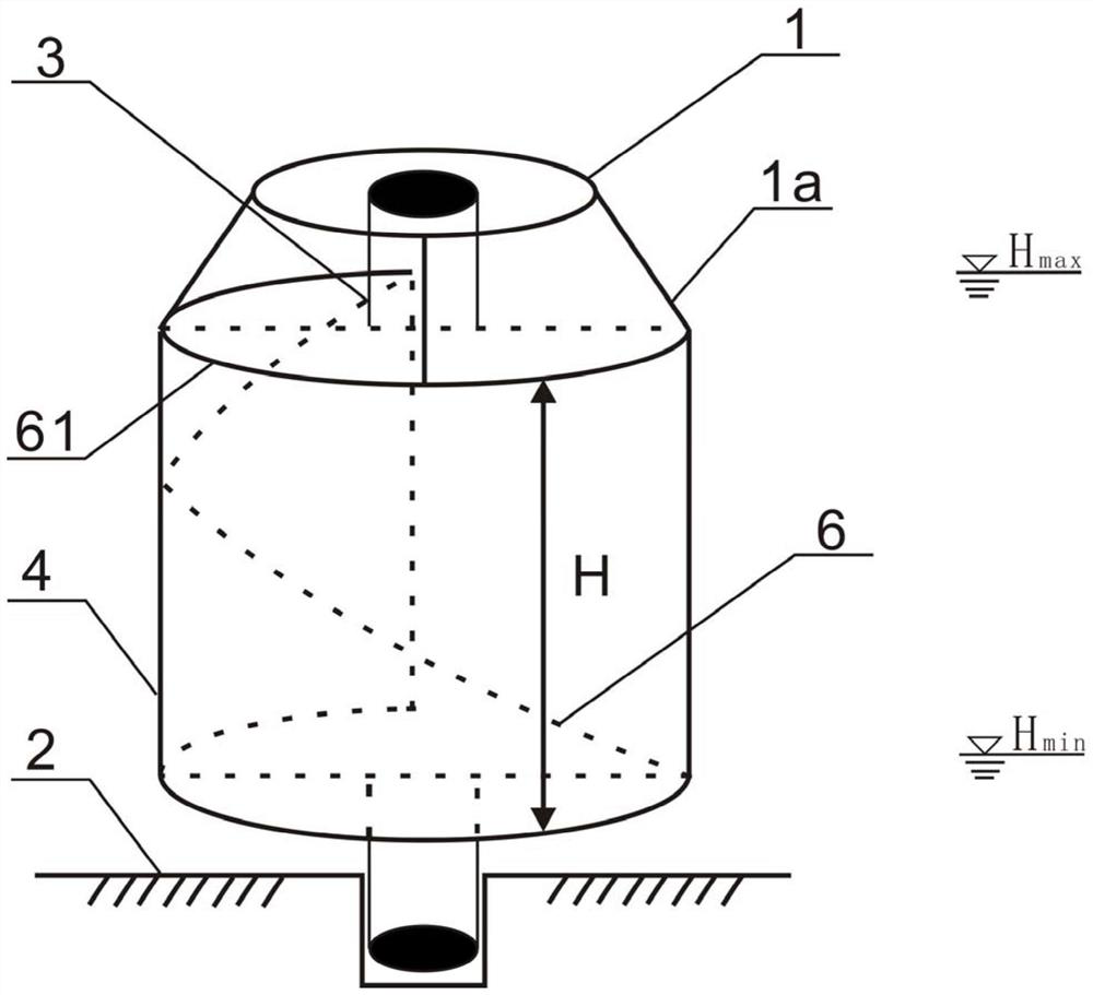
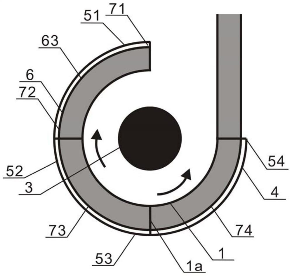
[0059] figure 1 It is a three-dimensional perspective schematic diagram of a fishway outlet system according to a preferred embodiment of the present invention. Such as figure 1 As shown, a fishway outlet system is adapted to adapt to changes in water levels. The fishway outlet system includes: a base 1 , a base 2 , a power shaft 3 , a fishway outlet section 6 and a rotating cylinder 4 . The base 2 is fixed on the bottom of the water, the upper end of the power shaft 3 is fixed on the base 1, the lower end of the power shaft 3 is rotatably fixed on the base 2, and the kinetic energy of the power shaft 3 is provided by the motor.

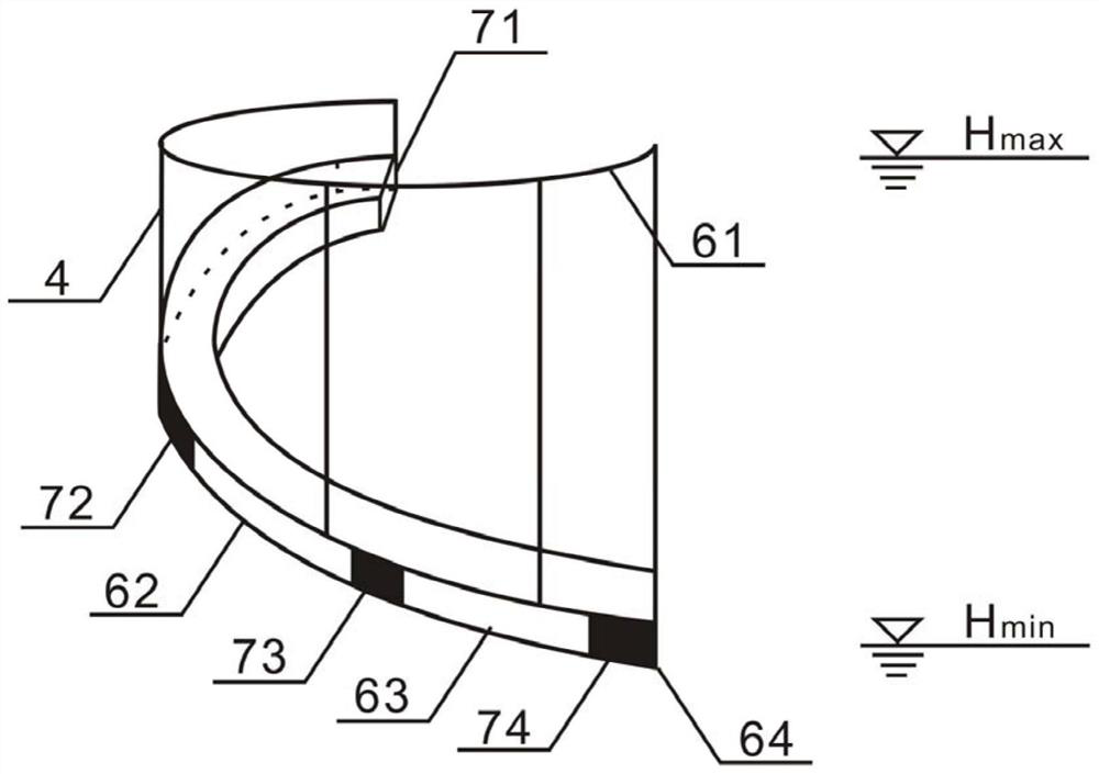
[0060] The fishway exit section 6 extends from bottom to top in the form of a cy...


PUM


Abstract

The invention discloses a fishway outlet system. The fishway outlet system adapts to water level change and comprises a base table, a base, a power shaft, a fishway outlet section and a rotating cylinder. The base is fixed to the water bottom, the upper end of the power shaft is fixed to the base table, and the lower end of the power shaft is rotatably fixed to the base. The fishway outlet sectionextends from bottom to top in a cylindrical spiral line mode, and multiple stages of fishway outlets are formed in the fishway side wall of the fishway outlet section. The top of the rotating cylinder is fixedly connected to the base table so as to be driven by the power shaft to rotate, the cylinder wall of the rotating cylinder is provided with multiple stages of outer wall openings, and the multiple stages of outer wall openings in the rotating cylinder correspond to the multiple stages of fishway outlets of the fishway outlet section, so that the multiple stages of fishway outlets can besequentially opened when the power shaft rotates the rotating cylinder. According to the fishway outlet system, opening and closing of a plurality of gates do not need to be switched, and only the rotating action of the rotating cylinder needs to be conducted.

Description

technical field [0001] The invention relates to the fields of water conservancy and hydropower engineering and ecological environment, in particular to a fish passage building, and more particularly to a fishway outlet system adaptable to water level changes. Background technique [0002] Fishway is an engineering measure to help fish go up. Building dams and other water conservancy projects on rivers cuts off the way for fish to migrate and spawn. By building fishways, fish can go up during the migration season, thereby Maintain the ecological balance of the river section. [0003] Fishway is a special facility to help fish pass through barriers such as dams smoothly, and plays an irreplaceable role in maintaining the continuity of rivers and the communication of biological populations. The success of fishway structures is one of the evaluation indicators for the health of the river ecosystem, and it is also an important evaluation indicator for ecological environment prot...

Claims


Application Information

Patent Timeline
Patent Type & Authority Applications(China)
IPC IPC(8): E02B8/08
CPCE02B8/08
Inventor 孙双科郑铁刚汪星戴会超石小涛戎贵文柳海涛李广宁张浩男江慧孟席何妙玲
Owner CHINA INST OF WATER RESOURCES & HYDROPOWER RES
Why Eureka
Try Eureka