Design method of porous scaffold with three-period minimal surface based on t-spline entity

A technology of extremely small curved surface and porous support, which is applied in the field of three-period minimally curved porous support design, can solve the problems of many calculation defects and low calculation efficiency, and achieve efficient and accurate subdivision, and the method is accurate, stable and reliable.

Active Publication Date: 2019-06-25
ZHEJIANG UNIV
View PDF5 Cites 0 Cited by
  • Summary
  • Abstract
  • Description
  • Claims
  • Application Information

AI Technical Summary

Problems solved by technology

[0008] In order to solve the shortcomings of low calculation efficiency and many calculation defects of the existing TPMS porous scaffold design method based on Boolean operations, the present invention provides a three-period minimal curved surface porous scaffold design method based on T-spline entities

Method used


Image

  • Design method of porous scaffold with three-period minimal surface based on t-spline entity
  • Design method of porous scaffold with three-period minimal surface based on t-spline entity
  • Design method of porous scaffold with three-period minimal surface based on t-spline entity

Examples


Embodiment 1

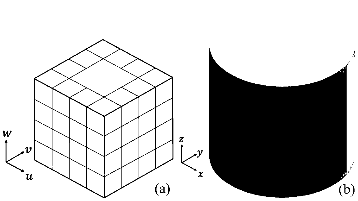
[0052] Select a liver T-spline solid model, such as Figure 5 (a) shown. The model is used to test the effect of the present invention to directly generate a uniform TPMS porous scaffold with a specific external shape by utilizing the T-spline entity parameter domain property. The model critical value control point C i are equal to 0, the periodic control point ω i are equal to 0.125, all component control points Q i (q iP ,q iG ,q iD )=(1,0,0), that is, only P surface is included.

[0053] Figure 5 (b) shows the uniform TPMS porous scaffold generated corresponding to the T-spline solid model of the liver in Example 1. It can be clearly seen that the porous structure has the same external shape as the initial input T-spline solid model, which avoids time-consuming Boolean operations and realizes the direct generation of TPMS porous scaffolds.

Embodiment 2

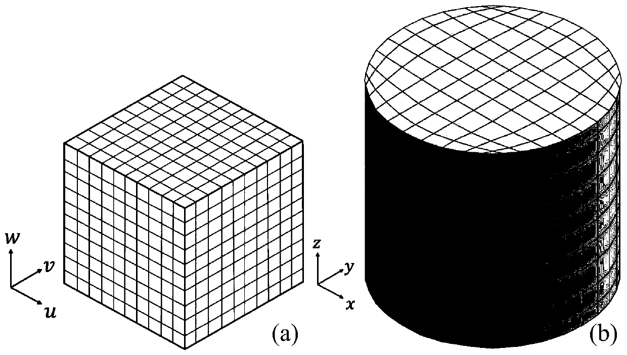
[0055] Select a femoral T-spline solid model, such as Figure 6 (a) shown. Considering the tissue engineering needs of different parts of the femoral scaffold, P surface, G surface and D surface were selected as the porous unit and the corresponding critical value and cycle in different parts. The final TPMS heterogeneous porous scaffold is as follows: Figure 6 (b) shown. It can be clearly seen that based on the method of T-spline solid control points and basis function mapping, heterogeneous TPMS porous scaffolds with complex internal shapes and specified external features can be generated, and the designer only needs to change the correlation of the control points at the required parts. parameters, which can correspond to the complex scaffold structure with controllable characteristics, which is especially suitable for the practical application of tissue engineering scaffold design, which illustrates the high efficiency of this method in designing porous scaffolds with thr...


PUM


Abstract

The invention discloses a three-period minimal-curved-surface porous scaffold designing method based on a T-spline entity. The method comprises the steps that a T-spline entity model to be processed is input; a parameter field is evenly divided to generate parameter field grids; vertexes of the parameter field grids are mapped into an Euclidean space to obtain mapped grids; according to three-period minimal-curved-surface critical values, periods and component control point coordinates, three-period minimal-curved-surface implicit function expression parameters corresponding to the vertexes of the parameter field grids are calculated; a movable cubic linear interpolation method is utilized to calculate an intersected triangular patch of an implicit curved surface and the mapped grids; finally the triangular patch obtained by calculating all interpolations is output in an STL file format for saving. High-freedom-degree design and rapid generation of a porous scaffold are achieved by utilizing T-spline entity control points and a primary function mapping method, the defects of time waste and lots of errors of a traditional Boolean operation method are overcome, and the method is especially suitable for porous scaffold design in tissue engineering.

Description

technical field [0001] The invention relates to the technical fields of computer aided design (CAD) and tissue engineering, in particular to a design method of a three-period minimally curved porous scaffold based on a T-spline entity. Background technique [0002] Tissue engineering technology is a popular technology in the field of regenerative medicine. With the help of growth factors, medical scientists cultivate human cells on tissue engineering scaffolds, grow into tissues and even organs with specific functions through cell proliferation and differentiation, and realize the restoration of human body defects. graft repair. Among them, tissue engineering scaffolds play a vital role in the process of cell proliferation and differentiation. As a support structure for cell growth, the scaffold should be a porous structure with a smooth surface and no twists or sharp edges to facilitate the attachment and growth of cells on the scaffold. In addition, porous scaffolds also...

Claims


Application Information

Patent Timeline
Patent Type & Authority Patents(China)
IPC IPC(8): G06F17/50G06T17/10
CPCG06F30/20G06T17/10
Inventor 傅建中冯嘉炜商策林志伟李斌
Owner ZHEJIANG UNIV
Why Eureka
Try Eureka