
A moving contact of an arc extinguishing chamber, an arc extinguishing chamber, and a high-voltage circuit breaker

A moving contact and interrupter technology, applied in high-voltage air circuit breakers, high-voltage/high-current switches, circuits, etc., can solve the problems of reduced sealing performance, large number of parts, and increased operating power of circuit breakers to achieve good sliding Effects of sealing performance, inner cavity volume reduction, and processing cost reduction

Active Publication Date: 2019-03-12
STATE GRID CORP OF CHINA +2
View PDF6 Cites 0 Cited by
  • Summary
  • Abstract
  • Description
  • Claims
  • Application Information

AI Technical Summary

Problems solved by technology

Simply adopting the sealing ring sealing structure has the hidden danger of reduced sealing performance after long-term wear and tear. Although the sealing ring plus sealing ring structure can compensate for the parts matching gap and the wear of the sealing ring, the sealing effect is relatively good, but the number of parts is relatively large. , and it will increase the friction force when the moving contact and the conductive seat move relative to each other, thereby increasing the operating work of the circuit breaker and increasing the operating load of the circuit breaker

Method used


Image

  • A moving contact of an arc extinguishing chamber, an arc extinguishing chamber, and a high-voltage circuit breaker
  • A moving contact of an arc extinguishing chamber, an arc extinguishing chamber, and a high-voltage circuit breaker

Examples


specific Embodiment 1

[0023] The first specific embodiment of the high-voltage circuit breaker of the present invention includes an arc extinguishing chamber. Since other structures do not involve the improvement of the present invention, a detailed description is omitted.

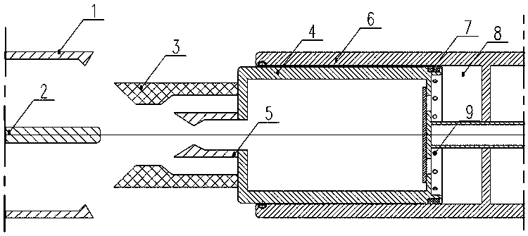
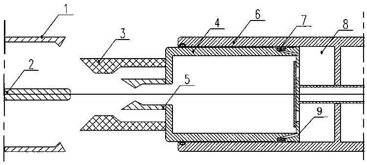
[0024] The structure of the interrupter is as figure 1 As shown, in this embodiment, the arc extinguishing chamber is a self-energizing arc extinguishing chamber, which includes moving and static contacts arranged oppositely. The static contact includes a static contact base 1 and a static contact 2. The moving contact includes a moving main contact 4 and a moving contact 5 and a nozzle 3 arranged at the front end of the moving main contact 4, that is, one end facing the static contact. The movable contact is mounted in the conductive base 6 for guiding movement, and is electrically connected to the conductive base 6 through a spring contact guide. The conductive seat 6 has a cylindrical structure, and the movable main contact 4 ...


PUM


Abstract

The invention provides an arc extinguish chamber movable contact, an arc extinguish chamber and a high-voltage circuit breaker. The arc extinguish chamber comprises a movable contact and a conductive base matched with the movable contact in a guiding and moving manner; the movable contact and the conductive base jointly form an air chamber in a surrounding manner; an annular mounting groove is formed in the matched surface, glidingly matched with the conductive base, of the movable contact; a sealing ring is mounted in the annular mounting groove; an air compressing channel connected with the annular mounting groove and the air chamber is also formed in the movable contact; and the air compressing channel is connected with the annular mounting groove through the groove bottom of the annular mounting groove and enables the gas in the air chamber to apply pressure to the sealing ring in a radial direction outwardly when the movable contact is in a switch-off action. When the movable contact is in a switch-off action, the size of the inner cavity of the air chamber is reduced; the internal air pressure is relatively high compared with the external air pressure, so that the sealing ring mounted in the annular mounting groove suffers from pressure from the groove bottom towards the conductive base, and the sealing ring and the conductive base can be matched more tightly; and therefore, high sliding and sealing performance between the movable contact and the conductive base is realized in the premise of not increasing the number of parts and not improving frictional force.

Description

Technical field [0001] The invention relates to the field of high-voltage switches, in particular to a movable contact of an arc extinguishing chamber, an arc extinguishing chamber and a high-voltage circuit breaker. Background technique [0002] High-voltage circuit breakers are divided into compressed air type, self-energy type and hybrid type according to the breaking principle, but there is a structure of air chamber in their structure, and its function is to rely on the movement of the movable contact to compress the hexafluoride in the air chamber. Sulfur gas is used to provide high-speed and high-pressure gas flow to extinguish the arc when it is switched off. Therefore, according to its principle, it is determined that all gas chambers need a sealed structure to reduce gas leakage loss during compression. [0003] The traditional air chamber sealing structure generally adopts a sealing ring or a sealing ring plus a sealing ring structure on the moving contact. The simple u...

Claims


Application Information

Patent Timeline
Patent Type & Authority Patents(China)
IPC IPC(8): H01H33/74
CPCH01H33/74
Inventor 韩峰赵海翔张敬涛王鹏超张帆王中华张锐刘通辉
Owner STATE GRID CORP OF CHINA
Learn More