Fuel battery gasket

A fuel cell and gasket technology, which is applied in the field of fuel cell gaskets, and can solve problems such as excessive compression of the gasket body 21

Active Publication Date: 2017-09-08
NOK CORP
View PDF9 Cites 0 Cited by
  • Summary
  • Abstract
  • Description
  • Claims
  • Application Information

AI Technical Summary

Problems solved by technology

[0004] While using the above image 3 In the case of the fuel cell gasket 11, the lip-shaped contact portion 23 of the first gasket main body 21 and the planar contact portion 33 of the second gasket main body 31 are formed to sandwich the intermediate member 54 when the battery cells are joined. However, as the intermediate member 54, when the joint load of the GDL56 arranged together with the MEA55 is small, the gasket main bodies 21 and 31 may be excessively compressed.

Method used


Image

  • Fuel battery gasket
  • Fuel battery gasket
  • Fuel battery gasket

Examples


Embodiment

[0035] Hereinafter, embodiments of the present invention will be described based on the drawings.

no. 1 example

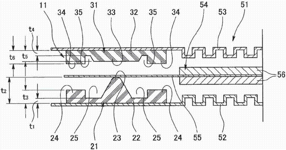
[0037] Such as figure 1 As shown, the fuel cell gasket 11 according to this embodiment includes an intermediate member 54 including an MEA (membrane electrode assembly) 55 and a GDL (gas diffusion layer) 56 installed between a pair of separators 52 and 53 . A gasket for a fuel cell unit 51 having a structure including a gasket main body (first gasket main body) 21 held on one separator 52 of a pair of separators 52, 53 and a gasket main body held on the other separator 52. The spacer main body (second spacer main body) 31 on the separator 53 is in contact with the MEA 55 of the intermediate member 54 at positions where the two spacer main bodies 21 , 31 overlap on a plane. The pad main bodies 21 and 31 are each formed of a predetermined rubber-like elastic body or the like.

[0038] exist figure 1 The first gasket main body 21 on the lower side is provided with a flat gasket base 22 and a lip-shaped contact portion 23 with a mountain-shaped cross section, and a mountain-sh...

no. 2 example

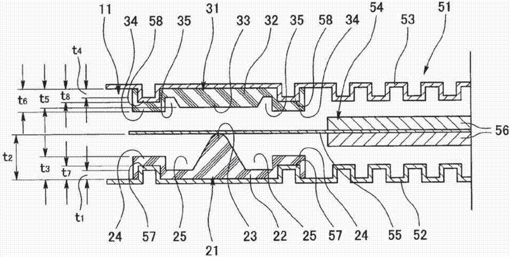
[0043] Next, in the fuel cell gasket 11 according to the second embodiment, on the basis of the same structure as the above-mentioned first embodiment, protrusions 57, 58 are provided on the respective separators 52, 53, and by The protrusions 57 and 58 support the banks 24 and 34 for standard size fixing. For example, the protrusions 57, 58 are formed into a hollow three-dimensional shape by pressing a part of the metal partition plates 52, 53, and the whole or a part (all in the figure) is buried in the embankments 24, 34 for standard size fixing. .

[0044] Therefore, according to this configuration, the softer material fixed size embankments 24 and 34 are supported by the harder material protrusions 57 and 58 , so that the standard size fixed dikes 24 and 34 can be suppressed from collapsing.

[0045] For the thickness (height) dimension t of the convex portion 57 7 , according to its function, the thickness dimension at the pad base 22 is t 1 , The thickness dimension ...


PUM


Abstract

The purpose of the present invention is, with respect to a configuration wherein contacting portions of gasket main bodies are compressed against one another in a manner that sandwiches a middle component during cell fastening, to prevent incidents of the gasket main bodies being compressed more than what is expected. In order to achieve this purpose, the gaskets equip a fuel battery cell wherein a middle part containing an MEA is intercalated between a pair of separators, the gaskets are for a fuel battery having a structure wherein, among the pair of separators, at a position on a plane where the gasket main body supported by one separator and the gasket main body supported by the other separator overlap, each enters in contact with the middle part, and the gaskets are characterized by each of the two gasket main bodies having, on both sides or on one side in the width direction thereof and formed in a single body therewith, a sizing stop dike portion pertaining to the gasket thickness size. In addition, the gaskets are characterized by each of the sizing stop dike portions being supported by a protruding portion provided on each of the separators.

Description

technical field [0001] The present invention relates to a fuel cell gasket constituting a sealing portion in a fuel cell unit. Background technique [0002] In fuel cell gaskets there are membrane face seals for sealing the ion exchange membranes and coolant seals for sealing the cooling side. As the assembly method of the gasket, there are the following methods: the gasket is integrally formed on battery cell parts such as separators, MEA, and GDL; the gasket is integrally formed on a resin reinforcement with an adhesive material and pasted on the separator. on battery cell parts such as plates; and independently forming and assembling the liner on the battery cell parts. As a method of joining battery stacks, there are a method of joining with a certain size (thickness dimension) and a method of joining with a certain load. Among them, as the latter, in the method of joining according to a certain load, it is necessary to consider the compression state of the GDL used an...

Claims


Application Information

Patent Timeline
IPC IPC(8): H01M8/0271H01M8/10H01M50/77
CPCH01M8/10H01M8/0271H01M8/0254H01M8/0276Y02E60/50H01M8/1004H01M2008/1095
Inventor 堀本隆之由井元
Owner NOK CORP
Why Eureka
Try Eureka