Multifunctional balance chair

A multifunctional and balanced technology, applied in the field of balance chairs, can solve problems such as discomfort for the sitter

Active Publication Date: 2017-09-12
叶龙华
View PDF12 Cites 3 Cited by
  • Summary
  • Abstract
  • Description
  • Claims
  • Application Information

AI Technical Summary

Problems solved by technology

Although this variable balance chair can be changed between the seat state and the balance chair, when it is used as a seat state, on the one hand, the existence of the knee and leg force pads will interfere with the placement of the sitter's legs, causing the sitter to On the other hand, if the area of ​​the seat board is too small, it will also cause discomfort to the sitter

Method used


Image

  • Multifunctional balance chair
  • Multifunctional balance chair
  • Multifunctional balance chair

Examples


Embodiment 1

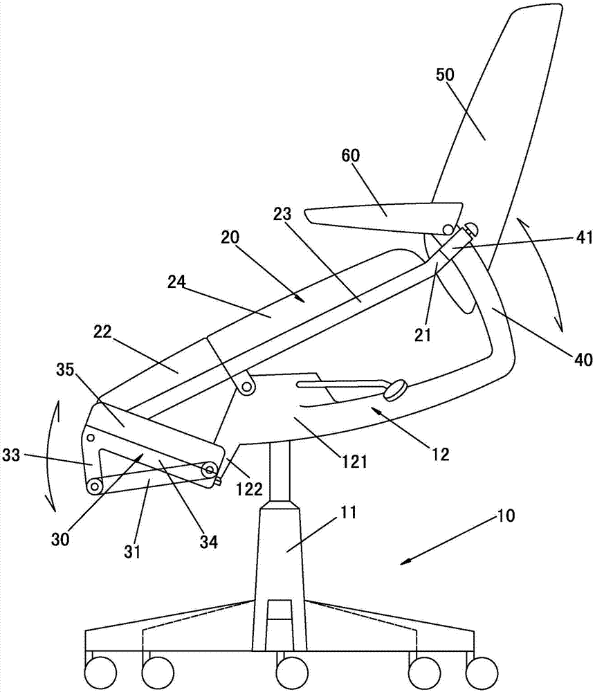
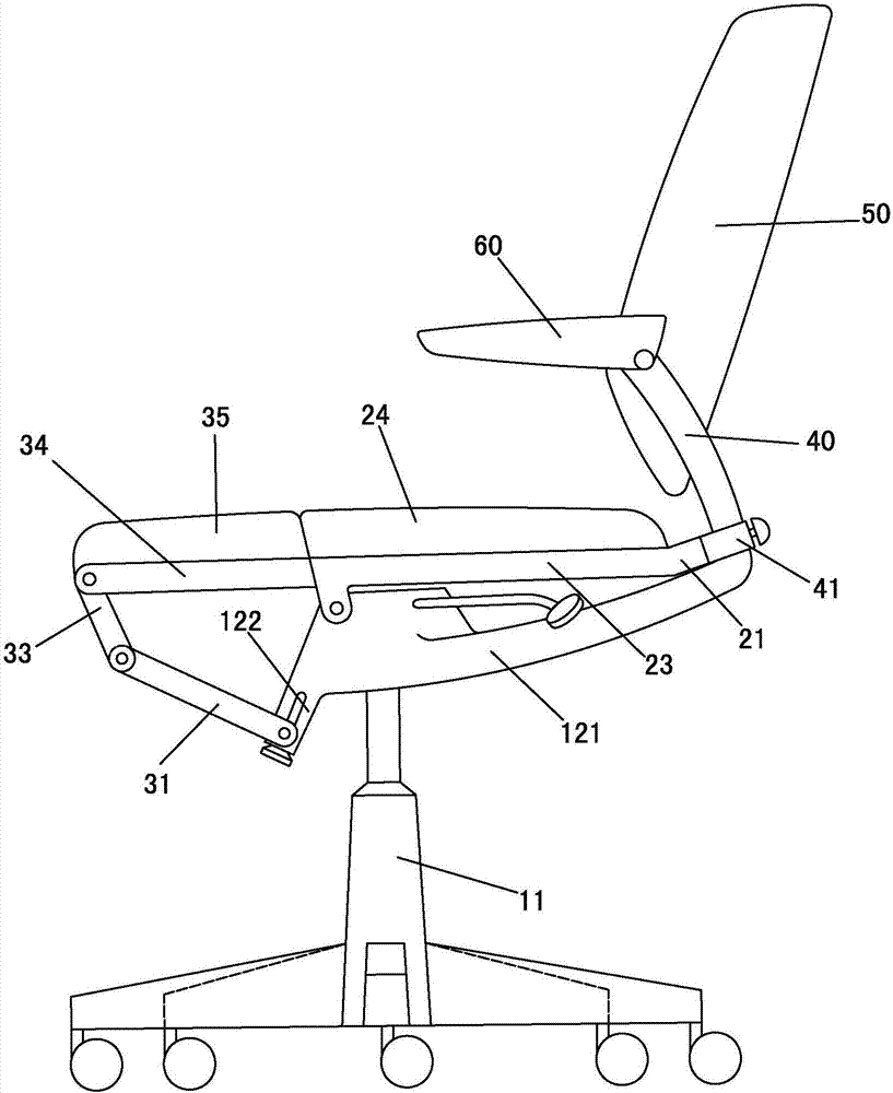
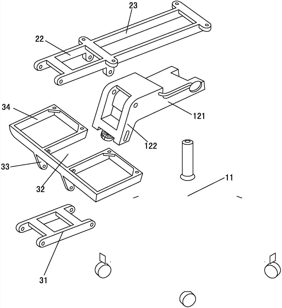
[0040] Please check Figure 1 to Figure 3 , a multifunctional balance chair, including a support part 10, a seat part 20 and a kneeling pad part 30, the seat part 20 can be rotatably connected to the support part 10 and can control the seat part 20 and the horizontal plane through the relative movement of the seat part 20 The kneeling pad part 30 can be rotatably connected to the seat part 20 and is connected to the support part 10 through the connecting mechanism, and the kneeling pad part 30 can be aligned between the position of the seat part 20 and the position of the kneeling cushion of the balance chair. The movement of the seat part 20 is linked with the movement of the kneeling pad part 30, so that the inclination angles of the kneeling pad part 30 and the seat part 20 are synchronously changed in opposite directions, and if the seat part 20 is tilted forward 30 "~40" angle lock complete change.

[0041] like figure 2 As shown, the kneeling pad part 30 is in a posit...

Embodiment 2

[0049] Please check Figure 4 to Figure 5 , it differs from the first embodiment in that: the support part 10 includes a herringbone leg 13 and a V-shaped seat 14, and the two open ends of the V-shaped seat 14 are respectively fixed on the upper part of the two legs of the herringbone leg 13; also Including a telescopic mechanism 70, one end of the telescopic mechanism 70 can be rotatably connected to the V-shaped seat 14 of the support part 10, and the other end can be rotatably connected to the rear support arm 25 fixed at the rear of the seat part 20. The telescopic mechanism 70 is as follows: It is a hydraulic cylinder mechanism; the other end of the synchronous connecting rod 31 is connected to the V-shaped seat 14 .

Embodiment 3

[0051] Please check Figures 6 to 8 , it differs from the first embodiment in that: the backrest 50 is provided with a second sliding rod 51 that can slide downward, and the lower end of the second sliding rod 51 can be rotatably connected to the rear of the disk body 121 fixed on the support part 10 The second rear support arm 123; the rear part of the seat cushion bridge 23 of the seat part 20 is rotatably connected to the backrest 50. The backrest 50 includes two backrest rods 52 and a backrest pad 53 fixedly connected between the two backrest rods 52. A telescopic structure is formed between the backrest rods 52 and the second sliding rod 51; the rear part of the seat cushion bridge 23 can be rotatably connected 52 on the backrest bar. Preferably, the backrest bar protrudes from the lower part of the backrest pad 53 .

[0052] According to requirements, a first locking mechanism is provided between the seat portion 20 and the supporting portion 1 (such as the tray body 1...


PUM


Abstract

The invention discloses a multifunctional balance chair. The multifunctional balance chair comprises a supporting portion, a seat portion and a knee cushion portion. The seat portion is movably connected to the supporting portion, and an included angle between the seat portion and the horizontal plane can be controlled through relative movement of the seat portion. The knee cushion portion is movably connected to the seat portion and further connected with the supporting portion through a connection mechanism, and linkage is realized by movement of the seat portion and the knee cushion portion. When the knee cushion portion is aligned to the seat portion, the multifunctional balance chair is in a state of a chair which is a common chair on the market, a seat portion of the chair comprises the chair seat portion and the knee cushion part, and accordingly a seat area is increased, and legs of a user are protected from interferences of the knee cushion portion. When the knee cushion portion is at a position for forming a knee cushion of the balance chair, the seat portion of the balance chair is inclined while an inclination surface faces forwards, the knee cushion portion is inclined while an inclination surface faces backwards, the user with knees on the knee cushion portion can sit on the seat portion to make the balance chair in a state of a common balance chair on the market.

Description

technical field [0001] The invention relates to a balance chair, in particular to a multifunctional balance chair. Background technique [0002] The traditional balance chair includes a leg frame, a backrest fixed on the leg frame, a seat part fixed on the leg frame, and a kneeling pad fixed on the leg frame. The balance chair has only a single function. Therefore there is room for improvement. [0003] In view of the above shortcomings, some people have proposed solutions, such as CN2390484Y published in the China Patent Database, a variable balance chair, including a seat plate, a bracket and a backrest. The seat plate and the bracket are connected by a positioning embedded connection method, and the knee and leg force pads are fixed at the brackets corresponding to the knees and legs when the human body is sitting. Although the variable balance chair can be changed between the seat state and the balance chair, when it is used as a seat state, on the one hand, the existe...

Claims


Application Information

Patent Timeline
Patent Type & Authority Applications(China)
IPC IPC(8): A47C3/00A47C7/50
CPCA47C3/00A47C7/50
Inventor 叶龙华
Owner 叶龙华
Why Eureka
Try Eureka