
Sheet laser back reflection synergism welding method for regulating back face energy field with auxiliary electric field

A welding method and auxiliary electric field technology, applied in laser welding equipment, welding equipment, metal processing and other directions, can solve the problems of high dispersion and poor directionality of the metal vapor cloud on the back, and achieve improved protection, efficiency, and good adaptation. sexual effect

Active Publication Date: 2017-09-15
苏州相王机械有限公司
View PDF5 Cites 5 Cited by
  • Summary
  • Abstract
  • Description
  • Claims
  • Application Information

AI Technical Summary

Problems solved by technology

[0005] The purpose of the present invention is to solve the problems of high dispersion and poor directionality of the metal vapor cloud on the back side of the back reflection synergistic laser welding of the metal sheet, and to invent a method of using a uniform electric field to regulate the dispersion degree and direction of the metal vapor cloud on the back of the welding sheet , so as to improve the efficiency of the back energy field and improve the protection effect of the back energy field on the back welding area. A thin plate laser back reflection synergistic welding method for regulating the back energy field by an auxiliary electric field

Method used


Image

  • Sheet laser back reflection synergism welding method for regulating back face energy field with auxiliary electric field
  • Sheet laser back reflection synergism welding method for regulating back face energy field with auxiliary electric field
  • Sheet laser back reflection synergism welding method for regulating back face energy field with auxiliary electric field

Examples


Embodiment Construction

[0031] The present invention will be further described below in conjunction with the accompanying drawings and embodiments.

[0032] Such as Figure 1-5 shown.

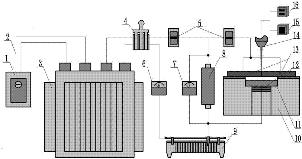
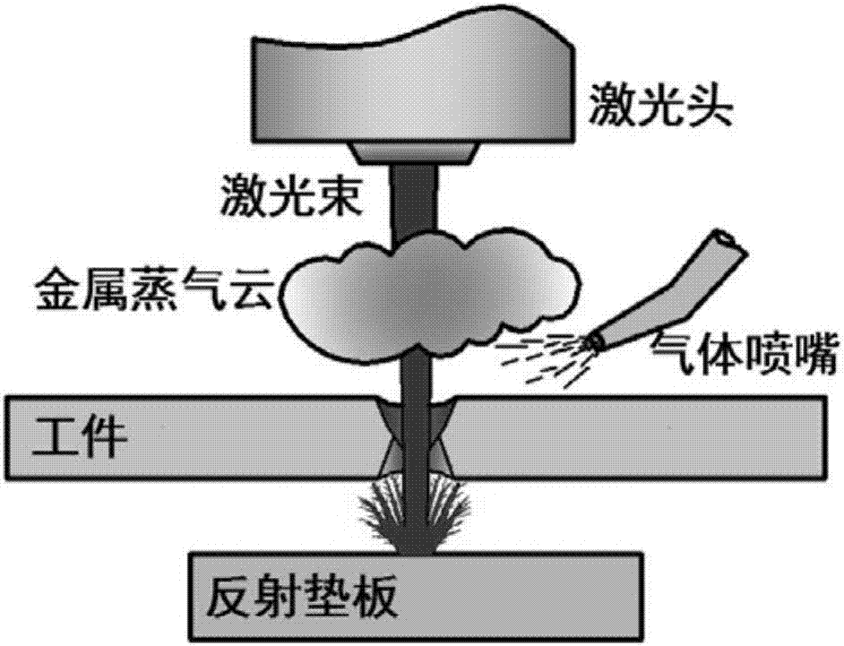
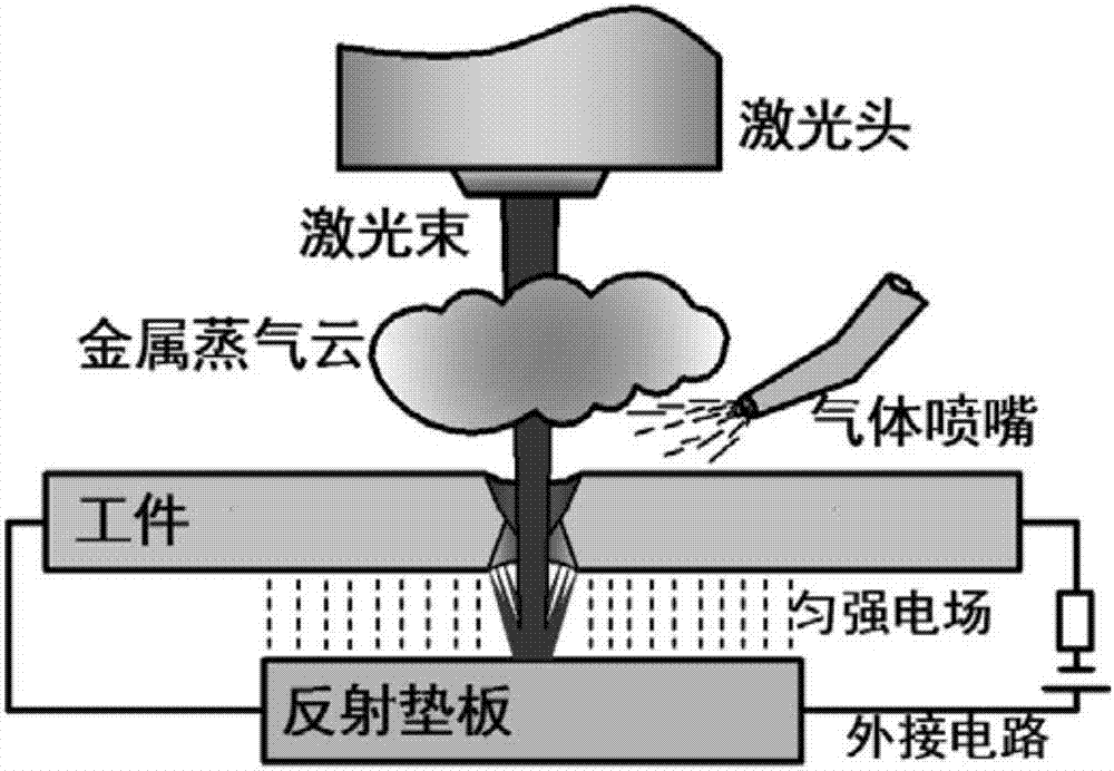
[0033] A thin-plate laser back reflection synergistic welding method with an auxiliary electric field to regulate the energy field on the back. The essence and key is to construct a parallel plate capacitor by introducing direct current between the welding thin plate and the reflective backing plate on the back, and use the parallel plate capacitor to generate a uniform electric field. The characteristics of the metal vapor cloud on the back of the weldment are regulated and regulated to ensure that the direction and concentration of the metal vapor cloud induced by the reflective backing plate are better when they return to the back welding area.

[0034] The specific steps are:

[0035] A) First convert the 220V AC to DC through a transformer rectifier;

[0036] B) After connecting the output terminal of the tran...


PUM


Abstract

The invention discloses a sheet laser back reflection synergism welding method for regulating a back face energy field with an auxiliary electric field. The sheet laser back reflection synergism welding method is characterized in that direct currents are introduced between a welded sheet and a reflection cushion plate on the back face to construct a parallel-plate capacitor; the characteristic that the parallel-plate capacitor generates the even-strength electric field is used for regulating the dispersion degree and directivity of a metal vapor cloud on the back face of a welded part, and therefore it is ensured that the directivity and the concentricity of the metal vapor cloud generated due to induction of the reflection cushion plate are good when the metal vapor cloud acts back to a back face welding area again; and thus, the efficiency of the back face energy field can be improved by 6%-14% compared with the efficiency generated when the auxiliary electric field is not additionally arranged, and the protection effect of the back face energy field on the back face welding area is improved.

Description

technical field [0001] The invention belongs to the technical field of laser welding, and relates to a metal thin plate laser back reflection synergistic welding method, in particular to a metal vapor cloud induced by a reflective backing plate on the back of a weldment by using a uniform electric field introduced on the back of the welding thin plate A thin plate laser back reflection synergistic welding method for regulating the back energy field by an auxiliary electric field that regulates the discrete degree and directionality of the formed back energy field. Background technique [0002] Laser welding has the advantages of good forming quality, small heat-affected zone, small workpiece deformation, and high flexibility. It is very suitable for welding and forming of metal sheets. As we all know, in the process of thin plate laser deep penetration welding, a higher laser energy threshold will inevitably lead to a higher temperature of the molten pool, which will lead to...

Claims


Application Information

Patent Timeline
Patent Type & Authority Applications(China)
IPC IPC(8): B23K26/24B23K26/70B23K26/14
CPCB23K26/1435B23K26/24B23K26/70B23K2101/18
Inventor 王宏宇赵前胥保文李乐张祥
Owner 苏州相王机械有限公司
Learn More