Film tearing device

A film device and film clip technology, applied in the directions of layered products, lamination auxiliary operations, lamination, etc., can solve the problems of low film tearing efficiency and achieve the effect of improving efficiency

Inactive Publication Date: 2017-09-15
KUSN JINGXUN ELECTRONICS TECH
View PDF5 Cites 4 Cited by
  • Summary
  • Abstract
  • Description
  • Claims
  • Application Information

AI Technical Summary

Problems solved by technology

[0003] The invention provides a film tearing device to solve the technical problem of low film tearing efficiency in the prior art

Method used


Image

  • Film tearing device
  • Film tearing device
  • Film tearing device

Examples


Embodiment Construction

[0011] In order to have a further understanding of the purpose, structure, features, and functions of the present invention, the following detailed descriptions are provided in conjunction with the embodiments.

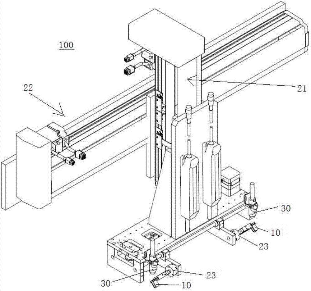
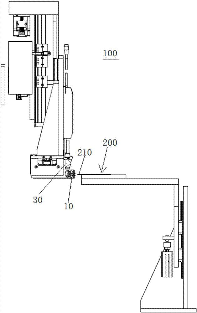
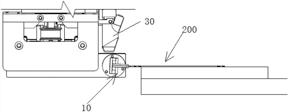
[0012] Please refer to figure 1 , figure 2 , figure 1 Is a schematic diagram of a film tearing device according to an embodiment of the present invention; figure 2 It is a side view of a film tearing device according to an embodiment of the present invention. The tearing device 100 of the present invention is used to tear off the protective film 220 with the tearing handle 210 on the product 200. The tearing device 100 includes a tearing clamp 10 and a positioning linkage unit for clamping the tearing film by using pneumatic power Handle 210; a positioning linkage unit for driving the film tearing fixture 10 to tear off the protective film 220 along an arc-shaped path. The positioning linkage unit specifically includes a Z-axis drive unit 21, a Y-axis drive unit 22, an...


PUM


Abstract

The invention provides a film tearing device, which is used to tear off the protective film with a film tearing handle on the product, and the film tearing device includes: a film tearing fixture, which is used to clamp the film tearing handle by using pneumatic power; a positioning linkage unit , used to drive the film tearing jig to tear off the protective film along an arc path. The film tearing device of the present invention drives the film tearing fixture to tear off the protective film along an arc-shaped path through the Z-axis driving unit and the R-axis driving unit, simulating the action of tearing the film by hand, and improving the efficiency of tearing the protective film.

Description

Technical field [0001] The invention relates to a film tearing device, in particular to a film tearing device that can simulate the action of a human hand. Background technique [0002] Currently, one of the processes in the LCD production process requires tearing off a layer of film attached to the glass substrate. The existing method of tearing the film is to manually tear off the film or the sticky roller. The existing manual tearing method is labor-intensive, highly dependent on the operator, very low in efficiency, and has a high probability of misoperation. Adhesive roller tearing film is to use adhesive tape for adhesive pulling to achieve the purpose of tearing off the protective film. The persistence of the stickiness of the sticky rollers in the prior art and the accuracy of the mechanical contact position will directly affect the success rate of the film tearing, and the sticky rollers have the problem of replacement cycle, resulting in poor operation of the equipment...

Claims


Application Information

Patent Timeline
Patent Type & Authority Applications(China)
IPC IPC(8): B32B38/10
CPCB32B38/10
Inventor 叶坤姜在焕
Owner KUSN JINGXUN ELECTRONICS TECH
Why Eureka
Try Eureka