Automatic knotting mechanism

An automatic knotting and rotating mechanism technology, which is applied in the field of knotting machines, can solve the problems of increasing enterprise costs, high labor intensity, and inability to overcome the limitations of manual knotting, so as to reduce labor intensity, reduce enterprise costs, and improve knotting efficiency effect with mass

Inactive Publication Date: 2017-09-15
DONGGUAN XINLIANGDIAN AUTOMATION EQUIP TECH
View PDF8 Cites 5 Cited by
  • Summary
  • Abstract
  • Description
  • Claims
  • Application Information

AI Technical Summary

Problems solved by technology

[0004] In view of the deficiencies in the existing technology, the purpose of the present invention is to provide an automatic knotting mechanism to solve the prob

Method used


Image

  • Automatic knotting mechanism

Examples


Embodiment Construction

[0017] In order to make the technical means, creative features, goals and effects achieved by the present invention easy to understand, the present invention will be further described below in conjunction with specific embodiments.

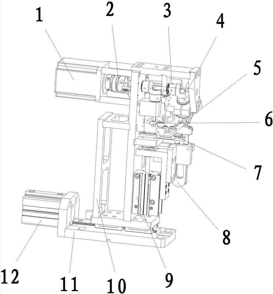
[0018] see figure 1 , the present invention provides an automatic knotting mechanism: its structure includes a servo motor 1, a rotating mechanism 2, a helical gear 3, a cam 4, a beak 5, a cam mechanism 6, a slider 7, scissors 8, a cutting cylinder 9, a fixed The plate frame 10, the positioning horizontal plate 11, and the propulsion cylinder 12, the right side of the propulsion cylinder 12 is installed on the left side of the positioning horizontal plate 11, the described rotating mechanism 2 is connected to the inside of the servo motor 1, and the described rotating mechanism 2. The right side runs through the fixed frame 10 and is connected with the helical gear 3. The cam 4 is installed on the upper end of the right side of the fixed frame 10....


PUM


Abstract

The invention discloses an automatic knotting mechanism. The mechanism structurally comprises a servo motor, a rotating mechanism, helical gears, a cam, a beak, a cam mechanism, a sliding block, scissors, a material cutting air cylinder, a fixed plate frame, a positioning transverse plate and a propelling air cylinder. The right side of the propelling air cylinder is installed on the left side of the positioning transverse plate, and the rotating mechanism is connected with the inside of the servo motor in a penetrating mode. The automatic knotting mechanism has the advantages that the knotting efficiency and quality are improved, and the two helical gears are driven by the servo motor, so that the beak and the sliding block work at the same time; an uneven contour makes a rope hooking sliding base hook and fix a rope, the rope hooking sliding base continuously moves forwards and backwards, the cam drives the thin rope wound on the closed beak to rotate, after the rope is wound by one circle, the beak is opened, the rope is clamped and pulled backward, a lever pulling action is carried out, a cylinder penetrates into a formed coil, a knot of the rope is tightened, and accordingly automatic knotting is achieved. The labor intensity is greatly reduced, and cost is reduced for enterprises.

Description

technical field [0001] The invention is an automatic knotting mechanism, which belongs to the field of knotting machines. Background technique [0002] At present, if the drawstring knots on the market are assembled manually, it is cumbersome and has a low error tolerance rate. Because the rope is flexible, manual knotting is too fast and easy to fail, wasting man-hours. Too slow and not very efficient, the whole step is too inefficient. The overall output cannot be kept stable for a long time. [0003] The prior art discloses a knotting machine with an application number of 2201210015019.4, which mainly includes a casing, which is flat and cuboid, hollow, with a connecting pipe at the bottom and a notch at the upper end of the casing. The side of the upper casing is chamfered. There is a machine head inside the casing. The length is greater than the length of the notch. There is a right-angle hook on the top of the machine head. The right-angle hook and the front of the...

Claims


Application Information

Patent Timeline
IPC IPC(8): D04G5/00
CPCD04G5/00
Inventor 张东升钟金
Owner DONGGUAN XINLIANGDIAN AUTOMATION EQUIP TECH
Why Eureka
Try Eureka