Speed changer and lubricating oil feeding device

A supply device, lubricating oil technology, applied in transmission parts, gear lubrication/cooling, belt/chain/gear, etc.

Inactive Publication Date: 2017-09-15
SCHAEFFLER TECH AG & CO KG
View PDF14 Cites 6 Cited by
  • Summary
  • Abstract
  • Description
  • Claims
  • Application Information

AI Technical Summary

Problems solved by technology

[0006] The problem solved by the present invention is that the lubricating oil supply mechanism in the existing transmission cannot provide enough lubricating oil for a long time to lubricate the components, resulting in wear of the components, which reduces the working performance and service life of the transmission

Method used


Image

  • Speed changer and lubricating oil feeding device
  • Speed changer and lubricating oil feeding device
  • Speed changer and lubricating oil feeding device

Examples


no. 1 example

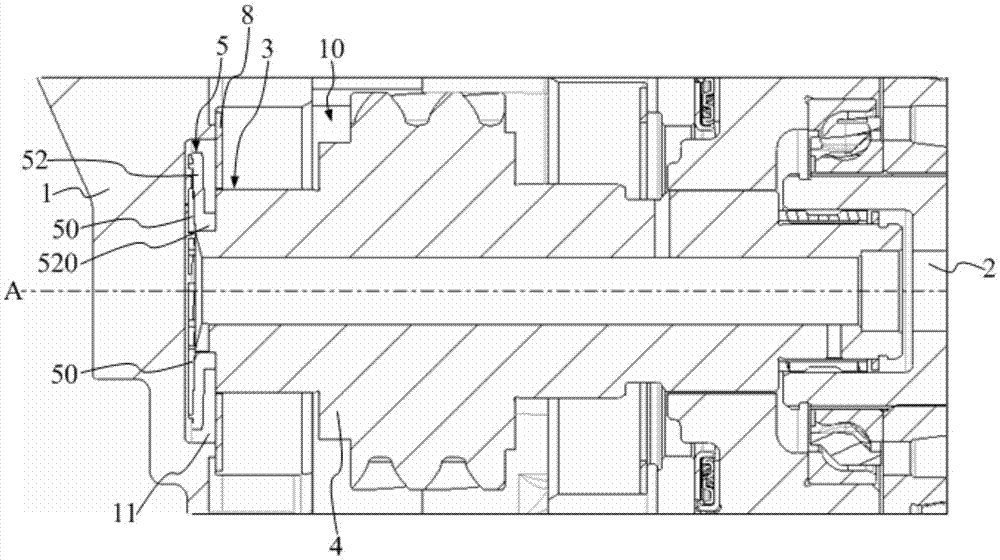
[0031] Reference figure 1 , The transmission includes: a transmission housing 1; an input shaft 2 and an output shaft (not shown in the figure) located in the transmission housing 1, which are arranged side by side; and a lubricating oil supply device 3.

[0032] The lubricating oil supply device includes: a housing with an inner cavity 10, which belongs to a part of the transmission housing 1. The inner wall of the transmission housing 1 is provided with an oil storage chamber 11; a hollow tube 4 is arranged in the inner cavity 10. It is connected to the transmission input shaft 2 and can rotate around its own central axis A under the drive of the transmission input shaft 2; The oil guide member 5 is at least partially located in the oil storage chamber 11 and connected to the hollow tube 4 for rotating around the hollow tube 4 under the drive of the hollow tube 4 to take and guide the lubricating oil in the oil storage chamber 11 to flow into Inside the hollow tube 4.

[0033] T...

no. 2 example

[0056] Compared with the first embodiment, the second embodiment is different in:

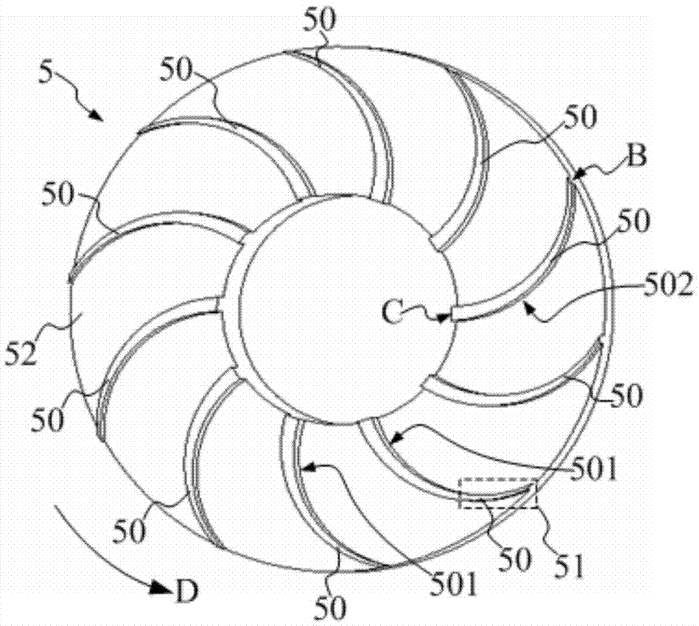
[0057] Reference Figure 5 , The blade 50' may have a hollow tube 4 (refer to figure 1 ), the oil guide groove 53 has an oil extraction port 530, and the direction of the oil extraction port 530 is the same as the rotation direction D of the hollow pipe 4. The lubricating oil enters the oil guide groove 53 from the oil extraction port 530 and flows into the hollow pipe 4 along the oil guide groove 53 when the blade 50 ′ rotates around the central axis of the hollow pipe 4. The opening of the oil extraction port 530 is set in the same direction as the rotation direction D of the hollow tube 4, so that the lubricating oil can enter the oil guide groove 53 through the oil extraction port 530 when the blade 50' rotates, and at the same time, when the blade 50' rotates from the lowest position During the rotation at the highest position, the lubricating oil will not leak from the oil guide groove 53. ...


PUM


Abstract

The invention discloses a speed changer and a lubricating oil feeding device. The lubricating oil feeding device comprises a housing, a hollow pipe and an oil guide piece; the housing is provided with an inner cavity; the hollow pipe is arranged in the inner cavity and can rotate around the central axis of the hollow pipe; an oil storage chamber is formed in the inner wall of the housing; and the oil guide piece is at least partly located in the oil storage chamber and is connected with the hollow pipe, and is used to rotate around the central axis of the hollow pipe under the driving of the hollow pipe, so as to collect and guide lubricating oil in the oil storage chamber to flow into the hollow pipe. According to the lubricating oil feeding device provided by the technical scheme, the oil guide piece is in contact with the lubricating oil in the oil storage chamber in a rotating process and collects the lubricating oil adhered to the oil guide piece. When the lubricating oil rotates from the lowest position to the highest position along with the oil guide piece, the lubricating oil flows into the hollow pipe due to the gravity and the action of the centripetal force. Even if the oil level of the lubricating oil in the oil storage chamber is low, the oil guide piece can be in contact with the lubricating oil along one end, far from the central axis in the radial direction, of the hollow pipe, and can collect and guide the lubricating oil to flow into the hollow pipe. In such technical scheme, no oil level of the lubricating oil in the oil storage chamber is required to reach a pipe opening of the hollow pipe.

Description

Technical field [0001] The invention relates to the technical field of motor vehicles, in particular to a transmission and a lubricating oil supply device. Background technique [0002] The transmission includes a transmission housing with an inner cavity, an input shaft and an output shaft located in the inner cavity, and a hollow tube coaxially connected to the input shaft. The hollow tube is coaxially connected to the output end of the input shaft for output The lubricating oil is delivered to the parts that need to be lubricated in the transmission, such as bearings and gears. [0003] The hollow pipe has an oil inlet, and an oil guide is arranged at the oil inlet. The oil guide includes an oil guide pipe connected to the oil inlet and an outer flange, and the outer flange is located at the end of the oil guide tube away from the oil inlet. The oil guide is fixed to the transmission housing in the radial direction by the outer flange, and the outer flange and the inner wall o...

Claims


Application Information

Patent Timeline
Patent Type & Authority Applications(China)
IPC IPC(8): F16H57/04
CPCF16H57/0427F16H57/0426F16H57/043F16H57/045F16H57/0457
Inventor 张小林陈春荣
Owner SCHAEFFLER TECH AG & CO KG
Why Eureka
Try Eureka