

Real-time monitoring, adjusting and controlling method for machine room operation energy consumption
A technology for real-time monitoring and operating energy consumption, applied in heating methods, heating and ventilation control systems, household heating, etc., can solve problems affecting the efficiency of water pumps, and achieve the effects of saving electricity expenses, easy operation, and reducing energy consumption
- Summary
- Abstract
- Description
- Claims
- Application Information
AI Technical Summary
Benefits of technology
Problems solved by technology
Method used
Image

Examples
Embodiment 1
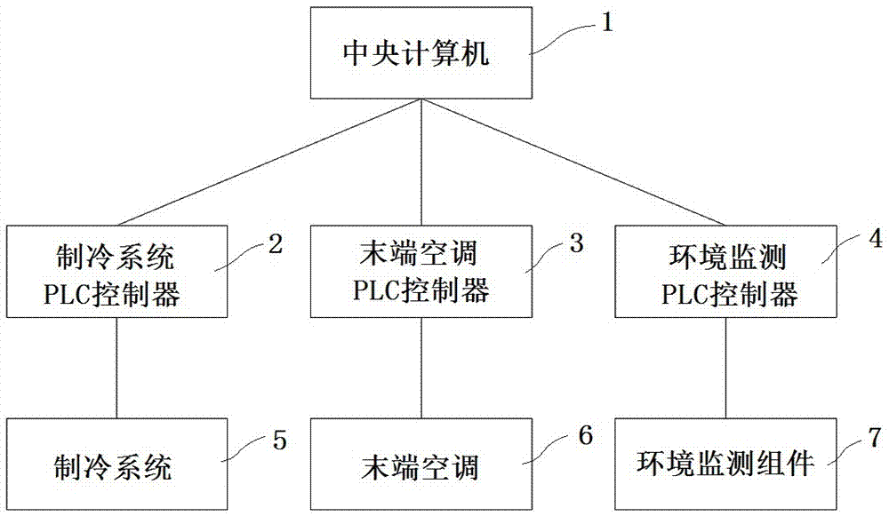
[0030] Such as figure 1 As shown, this embodiment specifically relates to a method for real-time monitoring and control of energy consumption in a machine room. The machine room here involves a refrigeration machine room and an IDC machine room. The real-time monitoring and control system applied to the real-time monitoring and control method includes a central computer 1, a refrigeration system PLC Controller 2, terminal air-conditioning PLC controller 3 and environmental monitoring PLC controller 4, each PLC controller is connected to the central computer 1, among which, the refrigeration system PLC controller 2 is connected to control the refrigeration system 5 (ie, the refrigeration room), and the terminal The air conditioner PLC controller 3 is connected to control each air conditioner 6 located in the IDC computer room, and the environment monitoring PLC controller 4 is connected to control the environment monitoring component 7 installed in the IDC computer room.
[003...
Embodiment 2
[0063] Such as figure 1 , 3 , 4, 6, and 7, this embodiment specifically relates to a method for real-time monitoring and control of energy consumption in a computer room. For the thermal imaging image in the computer room 12, the collected thermal imaging image is a three-dimensional thermal imaging image.
[0064] Such as figure 1 , 3 , 4, 6, and 7, the thermal imaging image obtained by scanning the infrared thermal vision scanning device 14 installed on the wall in the IDC machine room 12 is on a vertical plane, that is to say, the thermal imaging image obtained in Embodiment 1 The imaging map is only a two-dimensional image, and the staff cannot know its specific position along the depth direction of the cabinet 17; The thermal imaging image scanning on the inner horizontal plane; after the central computer 1 receives the thermal imaging image on the vertical plane and the thermal imaging image on the horizontal plane, the two are combined to obtain the three-dimensiona...
PUM
 Abstract
Description
Claims
Application Information