Paper money conveying device and automatic cash transaction device

A technology for conveying device and banknotes, which is applied to devices accepting coins, automatic teller machines, handling coins or valuable banknotes, etc., and can solve problems such as different bending directions.

Active Publication Date: 2017-09-15
SHENZHEN YIHUA COMP +2
View PDF9 Cites 1 Cited by
  • Summary
  • Abstract
  • Description
  • Claims
  • Application Information

AI Technical Summary

Problems solved by technology

[0004] In view of this, the present invention provides a banknote conveying device and an automatic cash transaction device to improve the existing banknote conveying device, which is prone to cause different bending directions of the banknote conveying device.

Method used


Image

  • Paper money conveying device and automatic cash transaction device
  • Paper money conveying device and automatic cash transaction device
  • Paper money conveying device and automatic cash transaction device

Examples


no. 1 example

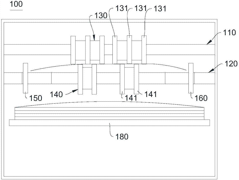
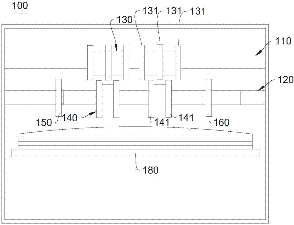
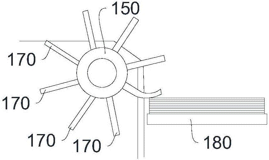
[0035] For details, see figure 1 , figure 1 It shows the banknote conveying device 100 provided by the first embodiment of the present invention. The banknote conveying device 100 includes a first rotating shaft 110, a second rotating shaft 120, a first rotating roller 130, a second rotating roller 140, a first impeller 150, a second impeller 160 and tray 180 .

[0036] The first rotating shaft 110 can be a cylindrical rotating shaft, both ends of the first rotating shaft 110 can be connected with the inner wall of the banknote conveying device 100 , and the first rotating shaft 110 can rotate relative to the inner wall of the banknote conveying device 100 .

[0037] The second rotating shaft 120 can also be a cylindrical rotating shaft, both ends of the second rotating shaft 120 are also connected to the inner wall of the banknote conveying device 100 , and the second rotating shaft 120 can also rotate relative to the inner wall of the banknote conveying device 100 . The ro...

no. 2 example

[0051] See Figure 5 , Figure 5 The internal structure of the automatic cash transaction device 200 provided by the second embodiment of the present invention is shown, which may include an access port 220, a temporary storage warehouse 230, an identification part 240, a conveying path 250 and the banknote conveying device in the first embodiment ( Figure 5 not shown). The banknote conveying device is provided in the access opening 220 . The deposit channel 221 of the access port 220 is connected to the identification unit 240 via the transport path 250 , and the identification unit 240 is connected to the temporary storage 230 via the transport path 250 . The temporary storage 230 is also connected to the take-out channel 222 of the access port 220 through another conveying path 250 .

[0052] The deposit and withdrawal port 220 is a part for exchanging banknotes with the user, and the user inserts banknotes as a medium when depositing. When withdrawing money, the depos...


PUM


Abstract

The embodiment of the invention provides a paper money conveying device and an automatic cash transaction device. The paper money conveying device comprises a first rotary shaft, a second rotary shaft, first rotating rollers, second rotating rollers, a first impeller and a second impeller. A preset angle exists between the first rotary shaft and the second rotary shaft, the first rotary shaft is sleeved with the first rotating rollers, and the second rotary shaft is sleeved with the second rotating rollers. The positions of the second rotating rollers correspond to that of the first rotating rollers respectively, and the second rotary shaft is sleeved with the first impeller and the second impeller. The first impeller and the second impeller are located on the two sides of the second rotating roller respectively. The first impeller and the second impeller both can slide in the axial direction of the second rotary shaft so that the paper money can be bent in the same direction, and moreover, the gaps between the paper money can be reduced by beating the paper money.

Description

technical field [0001] The invention relates to the field of banknote processing, in particular to a banknote conveying device and an automatic cash transaction device. Background technique [0002] The existing banknote conveying device will convey the banknotes through the opposite rotation of two adjacent conveying rollers, and after the banknotes are conveyed to the designated position, the banknotes will be slapped by the impeller arranged on the conveying rollers to reduce the gap between the banknotes. Clearance. [0003] Because the impellers of the existing banknote conveying devices are often elliptical, when the elliptical impeller rotates, it is easy to make the bending degree and bending direction of each banknote different, and the banknotes with different bending directions are stacked together so that the banknotes occupy The larger volume is not conducive to the storage of banknotes. Contents of the invention [0004] In view of this, the present inventi...

Claims


Application Information

Patent Timeline
IPC IPC(8): G07F19/00G07D11/00
CPCG07D11/17G07D11/175G07F19/20
Inventor 陈星
Owner SHENZHEN YIHUA COMP
Why Eureka
Try Eureka