Waterproof power supply switch

A power switch and electrode body technology, applied in electrical switches, magnetic field/electric field switches, magnetic switches, etc., can solve the problems of high security risks, the principle of waterproof power switches is old and not ideal, and achieves the effect of high safety

Inactive Publication Date: 2017-09-15
唐荣
View PDF6 Cites 2 Cited by
  • Summary
  • Abstract
  • Description
  • Claims
  • Application Information

AI Technical Summary

Problems solved by technology

[0002] The principle of the existing waterproof power switch is old and not ideal, especially in a humid environment where there is a greater potential safety hazard

Method used


Image

  • Waterproof power supply switch
  • Waterproof power supply switch

Examples


Embodiment Construction

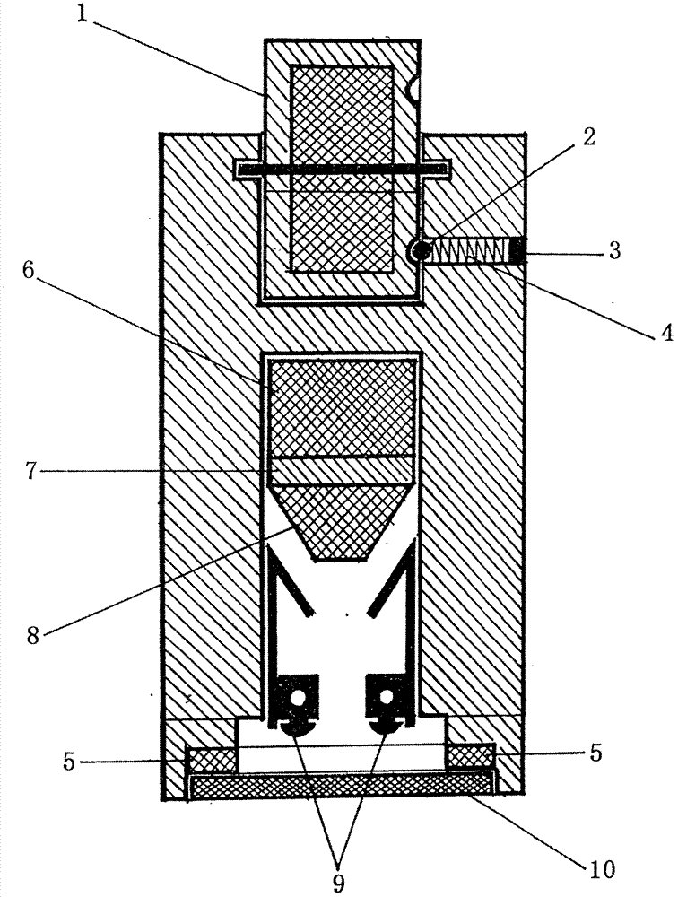
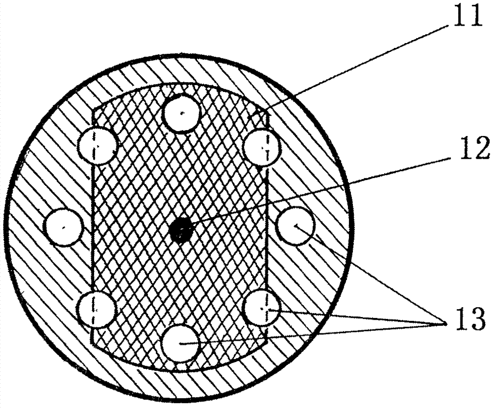
[0014] Such as figure 1 and figure 2 As shown, the present invention provides a waterproof power switch, including a wheel-shaped magnet 1, a positioning ball 2, a spring 4 and a blocking body 3, and a slider made up of a square magnet 6, an insulator 7 and a conductor 8; the slider Sliding in the chamber of the sealed chute, through the contact or disengagement of the conductor 8 on the slider and the electrode body 9, the purpose of turning on or breaking off the power supply is achieved.

[0015] When rotating the wheel-shaped magnet 1 to make the magnetic polarity of one end the same as the magnetic polarity of the square magnet 6 of the slider 2, the slider slides towards the electrode body 9, and the conductor 8 on the slider contacts the electrode body 9. At this time, the power supply is turned on, and the indicator light glows at the same time. When the magnetic polarity of the other end is opposite to that of the square magnet 6 on the slider when the wheel-shaped ...


PUM


Abstract

The invention relates to a waterproof power supply switch which comprises a wheel-shaped magnet, a positioning device, a magnet slider, an electrode body, a power on indicator, an exposed chamber and a sealing chamber. The wheel-shaped magnet comprises a bar-shaped magnet, a shaft bar and a positioning round pit. The magnet slider comprises a square magnet, an insulator and a conductor. The positioning device comprises a ball, a spring and a blocking body. The wheel-shaped magnet and the positioning device are exposed outside. The magnet slider and the electrode body are sealed in a chute chamber. The wheel-shaped magnet is rotated, so that the magnetic pole changes to drive the magnet slider to produce interaction to turn on or off a power supply.

Description

technical field [0001] The invention belongs to the field of electrical appliances, and in particular relates to a waterproof power switch. Background technique [0002] The principle of the existing waterproof power switch is outdated and not ideal, especially in a humid environment where there is a greater potential safety hazard. Contents of the invention [0003] In order to more scientifically solve the deficiencies in waterproofing of existing power switches, the present invention provides a new waterproof technology for power switches, which has a scientific principle, simple structure and high safety. [0004] The technical solution adopted in the present invention is: a waterproof power switch developed by using the magnetic polarity principle of the magnet, including a wheel-shaped magnet capable of rotating at an angle of 360°, a positioning device, a power-on indicator light, a magnet slider, an electrode body, and a set The bare chamber of the wheel magnet, t...

Claims


Application Information

Patent Timeline
Patent Type & Authority Applications(China)
IPC IPC(8): H01H36/00
CPCH01H36/0073
Inventor 唐荣
Owner 唐荣
Why Eureka
Try Eureka