Feeding device

A feeding device and feeding technology, applied in the field of feeding, can solve the problem that the feed cannot be prevented from sticking to the inner wall of the feeding frame, so as to achieve the effect of increasing the feeding rate and ensuring the feeding

Inactive Publication Date: 2021-04-06
姚方金
View PDF1 Cites 0 Cited by
  • Summary
  • Abstract
  • Description
  • Claims
  • Application Information

AI Technical Summary

Problems solved by technology

[0006] Aiming at the deficiencies of the prior art, the present invention provides a feeding device, which solves the problem that the device cannot prevent the feed from sticking to the inner wall of the feeding frame, effectively prevents the feed from sticking to the inner wall of the feeding frame, and prevents the feed from accumulating at the corners It prevents the chickens from eating, ach...

Method used


Image

  • Feeding device
  • Feeding device
  • Feeding device

Examples


Embodiment 1

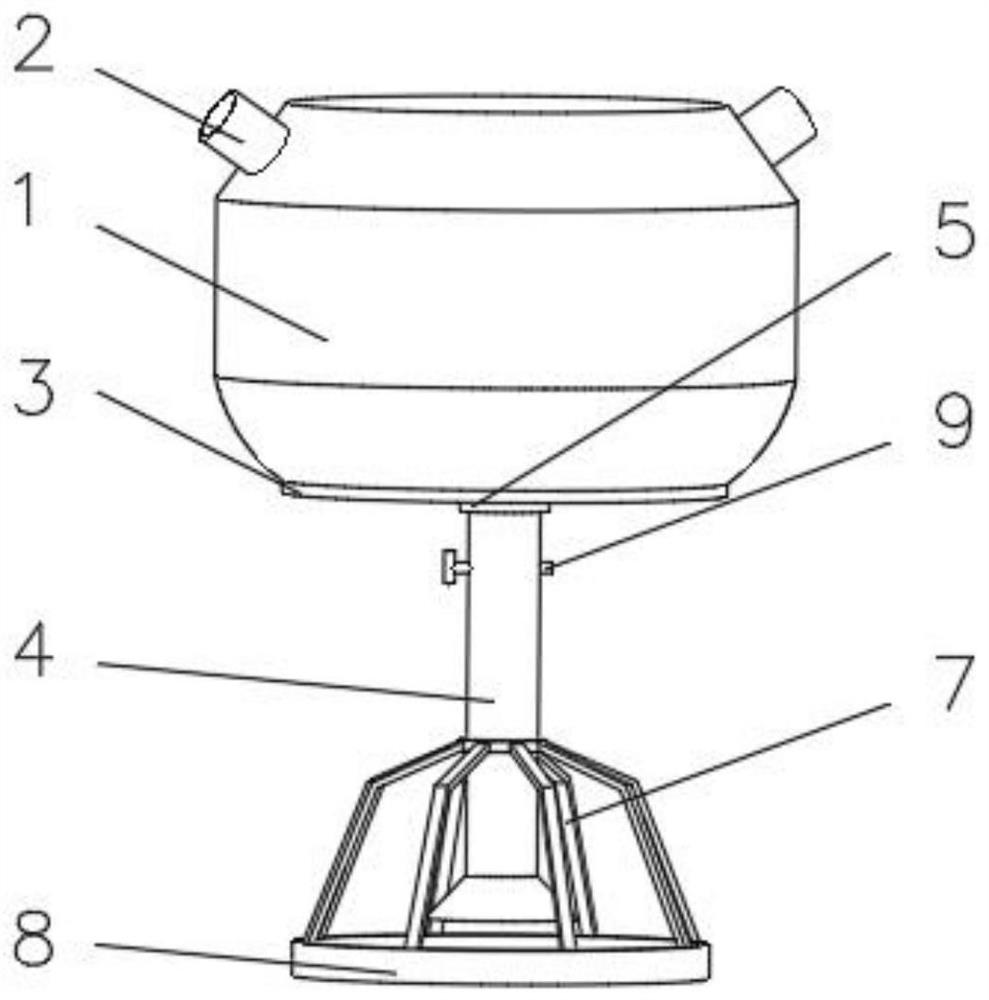
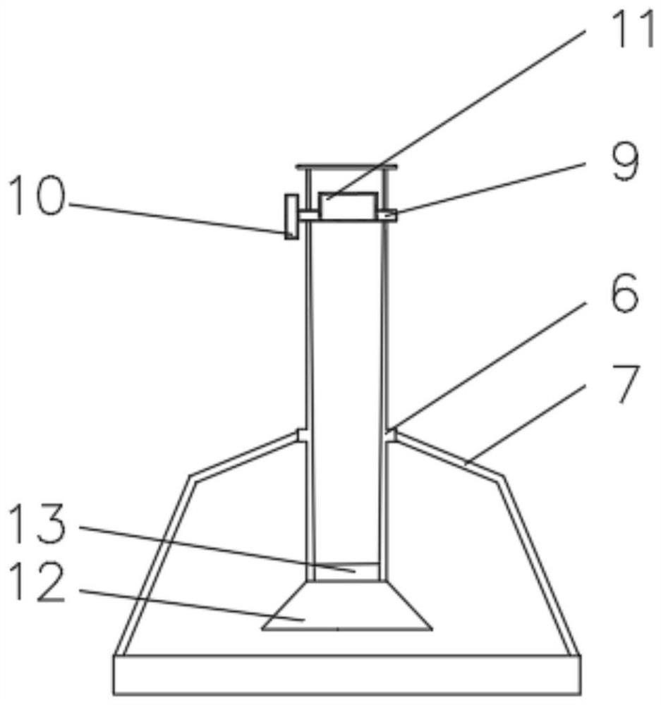
[0031] see Figure 1-3 , the present invention provides a technical solution: a feeding device, including a charging frame 1, one side of the charging frame 1 close to the top is connected with a feeding pipe 2, and one side of the charging frame 1 away from the feeding pipe 2 The bottom plate 3 is installed on the side, and the side of the charging frame 1 close to the bottom plate 3 is connected with the discharge pipe 4. The position of the discharge pipe 4 close to the bottom plate 3 is provided with a reinforcement ring 5, and the outer side of the discharge pipe 4 is provided with a fixed ring. 6. A bracket 7 is evenly installed on the side of the fixed ring 6 away from the discharge pipe 4, and the end of the bracket 7 away from the fixed ring 6 is fixedly connected with the feeding frame 8, and the side of the discharge pipe 4 is installed near the reinforcement ring 5. Rotating rod 9, one end of rotating rod 9 runs through the discharge pipe 4 and is fixedly connected...

Embodiment 2

[0038] see Figure 1-4 , the present invention provides a technical solution: on the basis of Embodiment 1, an arc-shaped baffle 17 is installed on the inner wall of the discharge pipe 4 close to the position of the rotating rod 9, and a scraper 18 is evenly installed on the inner side of the arc-shaped baffle 17 .

[0039] A rotating ring 19 is sleeved on one side of the rotating rod 9 close to the scraper blade 18 , and a fixing plate 20 is installed on one side of the rotating ring 19 .

[0040] A crushing device 11 is installed on one side of the rotating rod 9, and the crushing device 11 includes an outer frame 111, and one side of the outer frame 111 is provided with a groove 112, and the inner wall of the groove 112 is slidably connected with an extension plate 113 by a sliding rod 115, Blades 114 are evenly installed on one side of the extension plate 113 close to the groove 112 , and a discharge hole 116 is opened at the bottom of the outer frame 111 .

[0041] Duri...

Embodiment 3

[0044] see Figure 1-5 , the present invention provides a technical solution: on the basis of Embodiment 2, a stripping device 13 is installed on the inner wall of the discharge pipe 4 close to the baffle plate 12, and the stripping device 13 includes a first touch lever 131, the first One end of the touch lever 131 is rotatably connected to the discharge pipe 4, and a second touch lever 132 is installed on the inner wall of the discharge pipe 4 near the first touch lever 131, and the second touch lever 132 is close to the first touch lever. One side of 131 is equipped with a spring 133, and the end of the spring 133 away from the second touch bar 132 is fixedly connected with an elastic plate 134, and the side of the second touch bar 132 away from the spring 133 is equipped with an elastic bar 135, which is far away from the first One end of the two touch rods 132 is fixedly connected with the discharge pipe 4 .

[0045] When in use, when the feed falls into the inside of th...


PUM


Abstract

The invention discloses a feeding device, and relates to the technical field of feeding. The feeding device comprises a charging frame, wherein a feeding pipe communicates with the position, close to the top, of one side of the charging frame, a bottom plate is installed on the side, away from the feeding pipe, of the charging frame, a discharging pipe communicates with the side, close to the bottom plate, of the charging frame, and the position, close to the bottom plate, of the discharging pipe is sleeved with a reinforcing ring, the outer side of the discharging pipe is sleeved with a fixing ring, supports are evenly installed on the side, away from the discharging pipe, of the fixing ring, a feeding frame is fixedly connected to the ends, away from the fixing ring, of the supports, a rotating rod is installed at the position, close to the fixing ring, of one side of the discharging pipe, one end of the rotating rod penetrates through the discharging pipe and is fixedly connected to a rotating plate, and a crushing device is installed on one side of the rotating rod, and a baffle is installed at the end, close to the feeding frame, of the discharging pipe. According to the feeding device, feeds are effectively prevented from adhering to the inner wall of the feeding frame, and the phenomenon that the feed is accumulated at corners to hinder eating by chicks is avoided.

Description

technical field [0001] The invention relates to the technical field of feeding, in particular to a feeding device. Background technique [0002] Animal husbandry in the prior art usually adopts manual feeding, which is not only labor-intensive, but also causes a lot of waste of feed, which is not conducive to the economical utilization of resources. Therefore, it is necessary to develop an automatic feeding device for livestock. Improve the feed utilization rate and reduce the labor intensity of manual feeding. [0003] For example, Chinese patent CN110833041A proposes a kind of automatic feeding device, which belongs to the technical field of agricultural and animal husbandry machinery, especially a kind of automatic feeding device for livestock breeding feeding. The upper bracket is fixed on the upper end of the hopper inner wall, and the lower bracket is fixed on On the inner wall of the discharge pipe, the upper part of the screw is sleeved in the nut at the center of t...

Claims


Application Information

Patent Timeline
IPC IPC(8): A01K39/014A01K39/01B02C1/00B02C18/02B08B1/00
CPCA01K39/01A01K39/014B02C1/00B02C18/02B08B1/005
Inventor 王可文
Owner 姚方金
Why Eureka
Try Eureka