Flood control sewer well lid device for road

A road and manhole cover technology, which is applied in the field of flood control sewer manhole cover devices for roads, can solve problems such as flood drainage, achieve the effects of relieving pressure, promoting drainage, and preventing rolling deformation

Pending Publication Date: 2021-10-29
程洋
View PDF5 Cites 0 Cited by
  • Summary
  • Abstract
  • Description
  • Claims
  • Application Information

AI Technical Summary

Problems solved by technology

[0005] Aiming at the deficiencies of the prior art, the present invention provides a flood control sewer manhole cover device for roads, which solves the problem of flood drainage of the road manhole cover device

Method used


Image

  • Flood control sewer well lid device for road
  • Flood control sewer well lid device for road
  • Flood control sewer well lid device for road

Examples


Embodiment 1

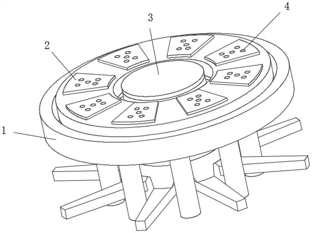
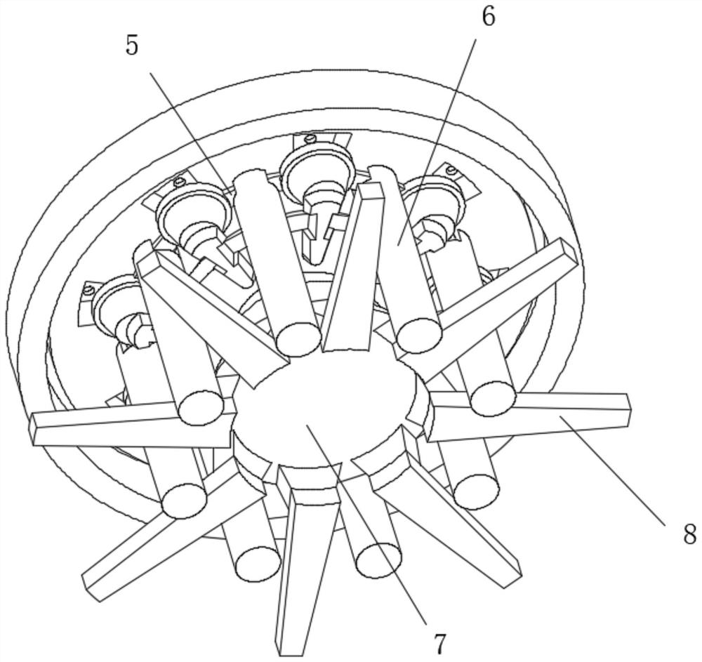
[0036] Such as Figure 1-5As shown, the present invention provides a technical solution: a road flood control sewer cover device, including a snap ring 1, the inside of the snap ring 1 is provided with a well cover 2, and the upper surface of the well cover 2 is fixedly connected with a baffle plate 4. A sinking sponge 3 is provided at the axis of the manhole cover 2, a fixing ring 5 is fixedly connected to the lower surface of the manhole cover 2, and a support column 6 is fixedly connected to the bottom of the fixing ring 5, and the sinking sponge The bottom of 3 is fixedly connected with a horizontal circular plate 10, and the bottoms at both ends of the horizontal circular plate 10 are fixedly connected with a water launching device 11. The sinking sponge 3 has a double-layer structure, the upper layer is hard plastic, and the lower layer is a high-quality water-absorbing sponge. The sewer cover device can discharge water into the sewer through the pores on the upper side ...

Embodiment 2

[0043] Such as Figure 6-7 As shown, on the basis of Embodiment 1, the present invention provides a technical solution: the impact cone device 8 includes a cone block 801, and the left side of the cone block 801 is fixedly connected to the surface of the bottom of the stabilizing plate 7, so The upper surface of the cone block 801 is fixedly connected with an arc thread 803, the outer surface of the cone block 801 is covered with a clip cover 802, and the right side of the clip cover 802 is fixedly connected with a sleeve block 804, the sleeve The right side of the block 804 is fixedly connected with a cone head device 805 . The pressure on the stabilizing disc 7 is given by the horizontal circular plate 10, and the stabilizing disc 7 is pressed so that the conical block 801 compresses the conical head device 805, so that the conical head device 805 penetrates into the soil layer to achieve the fixing effect, and the circular arc thread 803 can be in the cone When the head de...


PUM


Abstract

The invention discloses a flood control sewer well lid device for a road. The flood control sewer well lid device comprises a clamping ring, a well lid is arranged in the clamping ring in a sleeved mode, a baffle is fixedly connected to the upper surface of the well lid, a sinking sponge is arranged at the axis of the well lid, a fixing ring is fixedly connected to the lower surface of the well lid, and a supporting column is fixedly connected to the bottom of the fixing ring. The bottom of the sinking sponge is fixedly connected with a transverse circular plate, the bottoms of the two ends of the transverse circular plate are fixedly connected with water draining devices, the water draining devices are fixedly connected to concave holes in the bottom of the well lid, the bottom of the transverse circular plate is fixedly connected with first spring rods, and the bottom ends of the first spring rods are fixedly connected with stabilizing discs. The invention relates to the technical field of roads. According to the flood control sewer well lid device for the road, water flow can be drained into a sewer through the holes in the upper side of the baffle and the side edge of the sinking sponge, the number of sewer holes is large, and the problem that the well lid cannot drain water after the holes are blocked can be solved.

Description

technical field [0001] The invention relates to the technical field of roads, in particular to a flood control sewer cover device for roads. Background technique [0002] Road manhole cover devices can be seen everywhere in the streets and alleys of every city, part of which is used for sewer drainage, and part of which is used for the implementation of cables and other purposes. [0003] For the road manhole cover device for sewer drainage, in the case of sudden heavy rain, some places are low-lying, and the drainage capacity of the drainage manhole cover is limited, which will accumulate and form floods. After reaching a certain depth, vehicles will break down and pedestrians cannot wade through. dilemma. At the same time, due to the erosion of water, the manhole cover will settle quickly around the manhole cover, and over time, it will be sunken, resulting in uneven roads. Contents of the invention [0004] (1) Solved technical problems [0005] Aiming at the deficie...

Claims


Application Information

Patent Timeline
Patent Type & Authority Applications(China)
IPC IPC(8): E03F5/06E02D29/14
CPCE03F5/06E02D29/14E03F2005/068
Inventor 程洋
Owner 程洋
Why Eureka
Try Eureka