A mechanical valve with automatic shut-off function

A mechanical and functional technology, applied in the types of functional valves, mechanical equipment, fluid distribution valves, etc., can solve the problems of smaller valves, prolonged discharge time, and small valve flow.

Active Publication Date: 2022-05-31
浙江伟山机械有限公司
View PDF15 Cites 0 Cited by
  • Summary
  • Abstract
  • Description
  • Claims
  • Application Information

AI Technical Summary

Problems solved by technology

However, in the follow-up analysis, the inventor found that the valve has the following shortcomings: to a large extent, the flow of liquid flowing through the valve is determined by the distance between the valve core and the valve seat, so when the valve core faces the valve During the movement of the seat, since the distance between the two will become smaller and smaller, the valve flow will become smaller as the later stage progresses, that is, as the liquid in the container (or pool) increases, the valve core will Gradually move closer to the valve seat, so the flow rate of the valve will gradually decrease, and the final result is that the time of draining the liquid will be prolonged, and it will take longer for the liquid to reach the specified depth

Method used


Image

  • A mechanical valve with automatic shut-off function
  • A mechanical valve with automatic shut-off function
  • A mechanical valve with automatic shut-off function

Examples


Embodiment 1

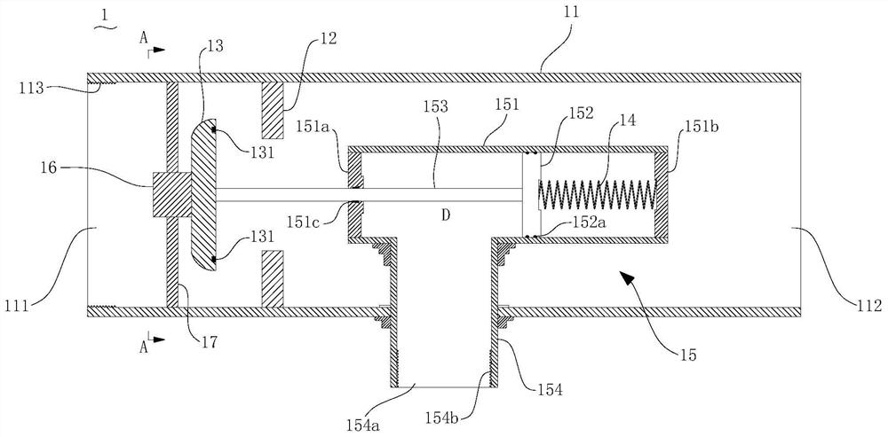
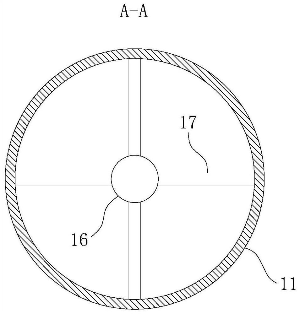
[0040] see Figure 1-Figure 3 As shown, the present invention provides a mechanical valve 1 with an automatic shut-off function, which includes a valve body 11 , a valve seat 12 , a valve core 13 , an elastic member 14 , a pneumatic mechanism 15 and a magnet 16 .

[0041] One end of the valve body 11 is the liquid inlet end 111 and the other end is the liquid outlet end 112 .

[0042] The valve seat 12 is arranged in the inner cavity of the valve body 11 .

[0043] The valve core 13 is arranged in the inner cavity of the valve body 11, and is used to interfere with the valve seat 12 to block the communication between the liquid inlet end 111 and the liquid outlet end 112 of the valve body 11, and the valve The core 13 is made of ferromagnetic material.

[0044] The elastic member 14 is used to impart a force to the valve core 13 to drive the valve core 13 to move to the side away from the valve seat 12;

[0045]The pneumatic mechanism 15 includes a cylinder 151 , a piston 1...

Embodiment 2

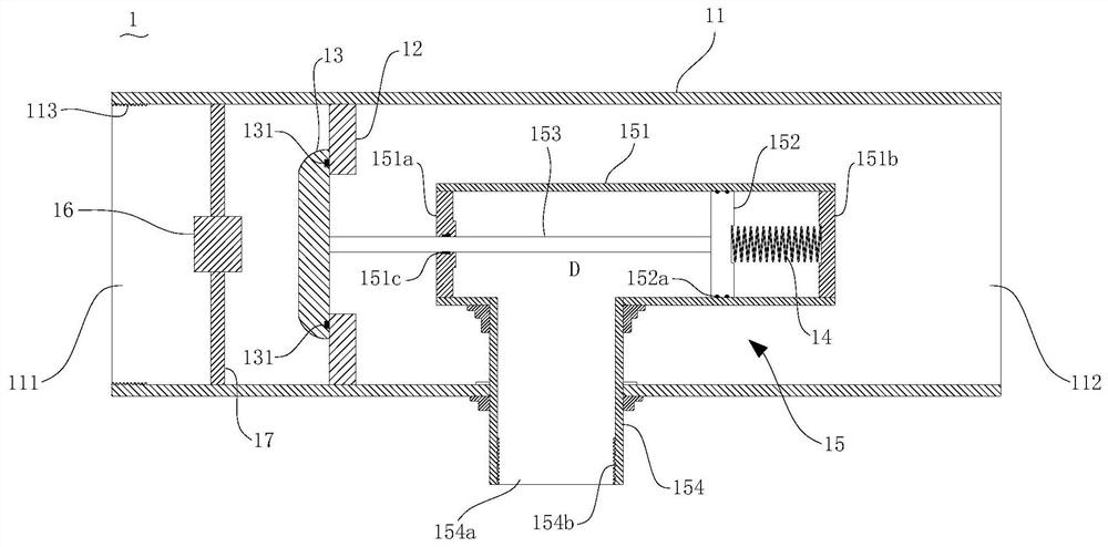
[0065] see Figure 4 As shown, the difference between this embodiment and Embodiment 1 is that the elastic member 14 is also a compression spring and is located in the cylinder 151, but one end of the elastic member 14 is fixed on the second end 151b of the cylinder 151, and the other is One end is the free end, which is not connected to the piston 152, and when the valve core 13 is adsorbed on the magnet 16, there is a distance between the free end of the elastic member 14 and the piston 152, which is usually greater than or equal to 2 cm.

[0066] the purpose of doing this is:

[0067] In Embodiment 1, when the valve core 13 is disengaged from the magnet 16, the piston 152 will immediately squeeze the elastic member 14, and after the elastic member 14 is squeezed, the N 2 will increase, so it will hinder the movement of the piston 152 and the valve core 13 to a certain extent. If the valve core 13 does not quickly leave the strong magnetic field area of ​​the magnet 16 at t...

Embodiment 3

[0069] see Figure 5 and Image 6 As shown, this embodiment provides a container, which includes a container body 2 and the valve 1 of the first embodiment or the second embodiment. The valve 1 is erected on the top of the container body 2 , and an extension pipe 3 is connected below the pipe body 154 of the valve 1 , and the extension pipe 3 extends to a position in the container body 2 near the bottom.

[0070] More specifically, the pipe body 154 of the valve 1 is connected with the extension pipe 3 through the first joint 4, and both ends of the first joint 4 have threads, which can be connected with the pipe body 154 and the extension pipe 3 respectively; The liquid inlet end 111 of the body 11 is connected with the liquid supply pipeline 6 through the second joint 5, and both ends of the second joint 5 have threads, which can be connected with the valve body 11 and the liquid supply pipeline 6 respectively; the liquid supply pipeline The front end of 6 is provided with...


PUM


Abstract

The invention discloses a mechanical valve with automatic cut-off function which can be applied in the production process of chemical materials, comprising a valve body, a valve seat, a valve core, elastic parts, a pneumatic mechanism and a magnet; the valve seat and the valve core are arranged In the valve body, the valve core is used to contact the valve seat to close the valve; the elastic member drives the valve core to maintain a distance from the valve seat; the pneumatic mechanism includes a cylinder, a piston, a piston rod and a pipe body, the cylinder is set in the valve body, and the piston is set in the In the cylinder, the two ends of the piston rod are respectively connected with the piston and the valve core, and one end of the pipe body is connected with the inner cavity of the cylinder, and the other extends to the outside of the valve body; the magnet is set on the side of the valve core away from the valve seat; the initial In the normal state, the valve core is adsorbed on the magnet. When the amount of gas entering the cylinder from the pipe body reaches a certain level, the air pressure of the gas will cause the valve core to separate from the magnet and then quickly fit on the valve seat. After using this valve, the flow cut-off of the valve occurs instantaneously, so there will be no situation that the flow rate becomes smaller and smaller during the flow cut-off process.

Description

technical field [0001] The invention relates to the field of valves, in particular to a mechanical valve with an automatic flow-off function. Background technique [0002] When water or other liquid materials are put into the pool or container through the pipeline, someone usually needs to stand by and wait for the liquid to reach the designated position, then close the valve and stop the liquid discharge. [0003] For example, in the production process of chemical materials, it is often necessary to put materials into containers for storage. During this process, a special person is required to wait by the side. Once the materials are full, the valve is closed, but when the volume of the container for storing materials is relatively large, the It will take a long time for the materials to be delivered, so the workers will have to wait for a long time; [0004] For another example, when water is put into the swimming pool, because the volume of the swimming pool is very larg...

Claims


Application Information

Patent Timeline
Patent Type & Authority Patents(China)
IPC IPC(8): F16K21/18
CPCF16K21/18
Inventor 陈蕾蕾
Owner 浙江伟山机械有限公司
Why Eureka
Try Eureka