An ion source etching device for realizing angle etching

A technology of etching equipment and ion source, which is applied to circuits, discharge tubes, electrical components, etc., can solve the problems of increasing the probability of ion source being polluted by particles, decreasing etching efficiency, and large distance gap, so as to solve the problem of etching Etch uniformity effect

Active Publication Date: 2019-03-29
BEIJING CHUANGSHI WEINA TECH
View PDF6 Cites 0 Cited by
  • Summary
  • Abstract
  • Description
  • Claims
  • Application Information

AI Technical Summary

Problems solved by technology

The angle adjustment and translation of the workpiece table are used to control the incident angle of the ion beam. Although the desired angle of the grating or the incident angle of the material can be achieved, the distance between the different positions of the workpiece and the ion source will be quite different. Obviously, in the etching During the process, the distance between the far end and near end of the inclination angle of the workpiece table and the ion source is very different (the two dimensions L1 and L2 in the figure), so that the workpiece at the far end and near end of the inclination angle of the workpiece table is etched There is a large difference in uniformity
Under such a scheme, the usual solution is to correct the uniformity by adding a "correction plate" on the incident channel of the etching ion beam between the ion source and the workpiece table. Although the "correction plate" can solve the problem of etching uniformity problem, but it brings two defects: First, after adding the "correction plate", the correction plate blocks a part of the ion beam, which reduces the etching efficiency. Generally, when the etching angle is 30°, the etching efficiency drops by 1 / 3 ; On the other hand, the "correction plate" is located on the etching channel, and is usually closer to the ion source. The etched particles of the correction plate will return to the ion source, increasing the probability of the ion source being contaminated by particles.
[0004] If another ion source angle etching scheme is used, the moving direction of the workpiece table is changed to form an angle with the ion source, that is, the workpiece table moves obliquely and gradually approaches the ion source, which can make the workpiece be etched at the same distance. etch, and ensure the uniformity without using the correction plate, but due to the large size of the workpiece and the etching angle to meet the etching at different angles, it is necessary to make the guide rails change at various angles, which will inevitably require a lot of unique vacuum chamber and complex mechanism to achieve

Method used


Image

  • An ion source etching device for realizing angle etching
  • An ion source etching device for realizing angle etching
  • An ion source etching device for realizing angle etching

Examples


Embodiment Construction

[0028] The present invention will be described in detail below in conjunction with the accompanying drawings and embodiments, wherein the accompanying drawings constitute a part of the application and are used together with the embodiments of the present invention to explain the present invention. But those skilled in the art should know that the following examples are not the sole limitation to the technical solution of the present invention, and any equivalent transformation or modification made under the spirit of the technical solution of the present invention should be considered as belonging to the protection of the present invention scope.

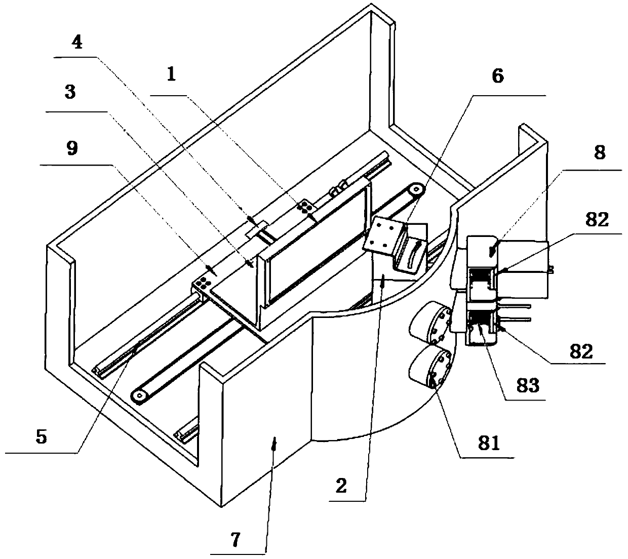
[0029] Such as figure 2 The illustrated embodiment is an ion source etching device for achieving angle etching, which mainly includes an ion source 2, a workpiece table 3, a first moving device 4, a second moving device 5, and a third moving device 6 , Vacuum chamber 7, Vacuum external connection device 8.

[0030] The workpiece ...


PUM


Abstract

The invention discloses ion source etching equipment for achieving angle etching. The ion source etching equipment comprises a vacuum chamber, wherein a workpiece and an ion source both are arranged in the vacuum chamber, a workbench is arranged in the vacuum chamber and is arranged on a first mobile device and a second mobile device, the first mobile device drives the workbench to forwards and backwards move relative to the ion source, the second mobile device drives the workbench to leftwards and rightwards move relative to the ion source, the ion source is arranged on a third mobile device, and the third mobile device drives the ion source to do angle conversion relative to the workpiece. A flexible connection piece is also arranged on an external pipeline and is used for applicable to uncomfortableness brought by angle adjustment on a hard pipe. By the ion source etching equipment, an existing design concept is changed, original angle rotation and adjustment of the workpiece is changed to angle rotation and adjustment of the ion source, thus, the problem of etching uniformity can be solved, and optimal range can also be ensured.

Description

technical field [0001] The invention relates to the fields of ion etching, holographic grating production and the like, in particular to the installation technology of ion source equipment for realizing angle etching. Background technique [0002] In the fields of ion beam etching, holographic grating production, etc., there must be a certain incident angle between the ion beam and the etched sample. On the one hand, it is due to the characteristics of the etched material that there must be an optimal etching incident angle. On the one hand, for applications such as holographic grating etching, the angle between the grating is related to the design of the light incident angle. [0003] The early ion source angle etching scheme was realized by using the rotation and translation of the workpiece table, and the exit direction of the ion source was always kept in the same direction. That is, the ion source was fixed and the angle and position of the etched workpiece were changed...

Claims


Application Information

Patent Timeline
Patent Type & Authority Patents(China)
IPC IPC(8): H01J37/08H01J37/147
CPCH01J37/08H01J37/147H01J2237/04H01J2237/08
Inventor 张少雷关江敏谢云
Owner BEIJING CHUANGSHI WEINA TECH
Why Eureka
Try Eureka