

Image compression framework combining super-resolution and residual coding technology
A coding technology and image compression technology, applied in the image compression framework combining super-resolution and residual coding technology, in the field of image super-resolution and image compression, to achieve the effect of improving quality, improving rate-distortion performance, and high compression rate
- Summary
- Abstract
- Description
- Claims
- Application Information
AI Technical Summary
Problems solved by technology
Method used
Image

Examples
Embodiment Construction
[0018] The present invention will be further described below in conjunction with accompanying drawing:
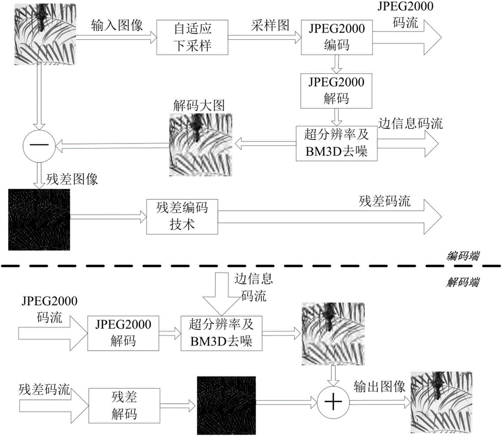
[0019] figure 1 , an image compression framework combining super-resolution and residual coding techniques, including the following steps:
[0020] (1) Iteratively back-projection downsamples the original image to be compressed to obtain a small image after sampling;
[0021] (2) At the encoding end, the small image is compressed by the JPEG2000 standard, and the code stream and denoising side information are transmitted to the decoding end;
[0022] (3) Obtain the decoded small image at the decoding end, and reconstruct the small image into a decoded large image through super-resolution based on code rate classification;
[0023] (4) Combining the denoising side information to suppress the compression noise in the decoded large image and improve the quality of the decoded large image;
[0024] (5) Calculate the residual of the decoded large image and the original image ...
PUM
 Abstract
Description
Claims
Application Information