Bending die for Z-shaped part

A technology of bending dies and punches, which is applied in the direction of metal processing equipment, forming tools, manufacturing tools, etc., can solve problems such as easy sliding of blanks, and achieve the effect of preventing deviation

Inactive Publication Date: 2017-09-22
SUZHOU HUALAI PHOTOELECTRIC INSTR
View PDF0 Cites 3 Cited by
  • Summary
  • Abstract
  • Description
  • Claims
  • Application Information

AI Technical Summary

Problems solved by technology

[0002] At present, the existing simple Z-shaped parts can be formed by one bending, but because there is no pressing device, the blank is easy to slide during bending, so it is only suitable for parts with low requirements

Method used


Image

  • Bending die for Z-shaped part

Examples


Embodiment Construction

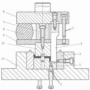
[0018] The present invention will be further described below in conjunction with the accompanying drawings.

[0019] Such as figure 1 As shown, a Z-shaped piece bending die includes a top plate 1, a positioning pin 2, a reverse side pressing block 3, a punch 4, a guide column 5, an upper die seat 6, a pressing block 7, a rubber 8, a punch supporting plate 9, Movable punch 10, lower die holder 11. The top plate 1 is movably connected to the lower die base 11 through a push rod, the punch 4 is fixed on the upper die base 6, the lower end of the punch 4 passes through the punch support plate 9, and the lower end of the punch 4 is aligned with the position on the right side of the top plate 1. Corresponding; the movable punch 10 is movably connected to the upper die base 6 through the punch supporting plate 9, the lower end of the movable punch 10 corresponds to the position on the left side of the top plate 1, and a rubber is set between the upper die base 6 and the punch suppor...


PUM


Abstract

The invention discloses a Z-shaped piece bending die, which comprises a top plate, a punch, an upper die base, a rubber, a punch supporting plate, a movable punch, and a lower die base; the top plate is movably connected to the lower die base through a push rod, and the punch Fixed on the upper die base, the lower end of the punch passes through the punch support plate, and the lower end of the punch corresponds to the position on the right side of the top plate; the movable punch is movably connected to the upper die base through the punch support plate, and the movable punch The lower end of the lower end corresponds to the position on the left side of the top plate, and a rubber is set between the upper die seat and the punch supporting plate; before stamping, the movable punch is flush with the end face of the punch under the action of the rubber; when stamping, the movable punch and the top plate will be The billet is pressed tightly, because the elastic force generated by the rubber is greater than the elastic force generated by the buffer under the top plate, pushing the top plate down to make the left end of the blank bend; Move down to bend the right end of the blank into shape.

Description

technical field [0001] The invention relates to a Z-shaped piece bending die. Background technique [0002] At present, the existing simple Z-shaped parts can be formed by one bending, but because there is no pressing device, the blank is easy to slide during bending, so it is only suitable for parts with low requirements. Contents of the invention [0003] Purpose: In order to overcome the deficiencies in the prior art, the present invention provides a Z-shaped bending die. [0004] Technical solution: In order to solve the above-mentioned technical problems, the technical solution adopted in the present invention is: [0005] A Z-shaped piece bending die is characterized in that it includes a top plate, a punch, an upper die holder, a rubber, a punch support plate, a movable punch, and a lower die holder; [0006] The top plate is movably connected to the lower mold base through the push rod, the punch is fixed on the upper mold base, the lower end of the punch passes ...

Claims


Application Information

Patent Timeline
Patent Type & Authority Applications(China)
IPC IPC(8): B21D37/10
CPCB21D37/10
Inventor 薛文英
Owner SUZHOU HUALAI PHOTOELECTRIC INSTR
Why Eureka
Try Eureka