
Underwater concrete pouring piling machine

A technology of underwater concrete and pile driving, which is applied in construction, sheet pile walls, foundation structure engineering, etc. It can solve problems such as failure to meet requirements, troublesome control, and failure to meet production needs, so as to achieve automatic control and reduce labor and the effect of material loss

Inactive Publication Date: 2017-09-22
SUZHOU TANGSHI JIANHUA CONCRETE PILE
View PDF4 Cites 4 Cited by
  • Summary
  • Abstract
  • Description
  • Claims
  • Application Information

AI Technical Summary

Problems solved by technology

[0005] The existing underwater concrete pouring pile machines are all artificial fillers during control, which is troublesome to control and easily fails to meet the requirements, which can no longer meet the current production needs

Method used


Image

  • Underwater concrete pouring piling machine

Examples


Embodiment 1

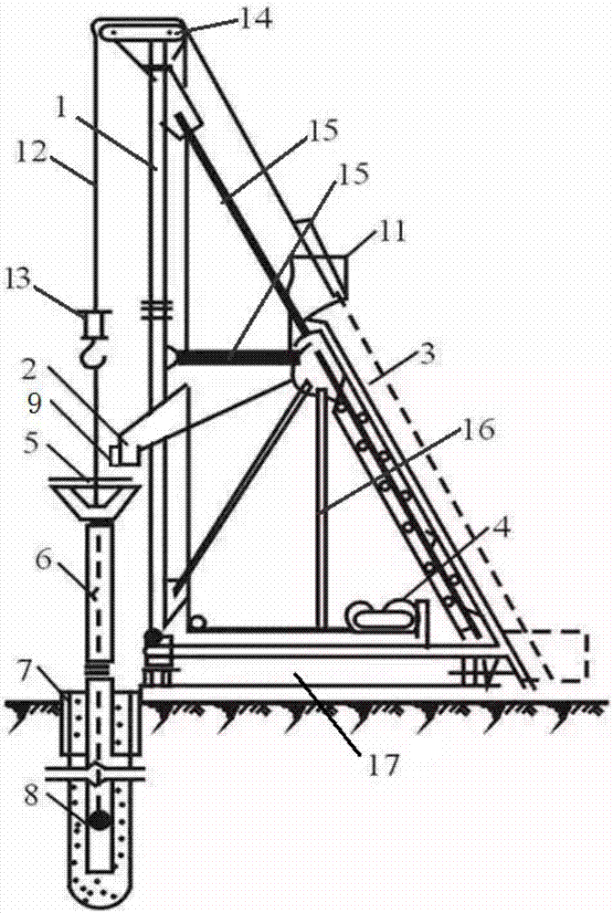
[0020] like figure 1 The shown a kind of underwater concrete pouring pile driver of the present invention comprises a machine base 17, a frame 1 is arranged vertically on the said machine base 17, and a conveyor belt 3 is arranged on the rear side of the said machine base 17 obliquely, so that The upper end of the conveyor belt 3 is provided with a cover plate 11, the lower side of the feeding port of the conveyor belt is provided with a feeding hopper 2, the upper end of the frame 1 is also provided with a wheel plate 14, and a cable is slidably arranged on the wheel plate 14. Line 12, the lower end of the cable 12 is connected with a hook 13, the lower end of the hook 13 is hung with a funnel 5 by a sling, the funnel 5 is located below the feeding hopper 2, and the feeding hopper 2 faces Funnel 5 direction is provided with inductor 9, and this inductor 9 selects the inductor 9 that can sense object distance, is used for sensing the height of material in funnel 5, and the low...


PUM


Abstract

The invention relates to an underwater concrete pouring piling machine. A rack is vertically arranged on a machine base; a conveying belt is obliquely arranged on the rear side of the machine base; a cover plate is arranged at the upper end of the conveying belt; a feeding funnel is arranged on the lower side of a feeding mouth of the conveying belt; a wheel plate is arranged at the upper end of the rack; a cable is slidingly arranged on the wheel plate; the lower end of the cable is connected with a lifting hook; a hopper is hung at the lower end of the lifting hook through a lifting rope, and is located below the feeding funnel; an inductor is arranged on the feeding funnel and faces towards the hopper; the lower end of the hopper is connected with a plurality of sections of conduits; one conduit at the endmost is internally provided with a bulb stopper; the conveying belt is driven by a driving device; the driving device is connected with a controller; and the inductor is connected with the controller. The inductor is arranged on the feeding funnel, when the hopper is filled with concrete, the driving device is stopped through the controller and then the conveying belt stops feeding, and when the concrete is reduced to be in the bottom position, the feeding begins again, so that in a continuous pouring process, automation control is realized, and labor and material losses are reduced.

Description

technical field [0001] The invention relates to an underwater concrete pouring pile driver, which belongs to the field of concrete machinery equipment. Background technique [0002] Concrete that is mixed in a dry place and poured and hardened underwater is called underwater concrete. Although concrete can solidify and harden underwater, the pouring quality is poor. Therefore, only in the case of last resort, or in the underwater part of some secondary buildings, the method of underwater pouring is adopted. The requirements for underwater pouring concrete are relatively high, and must have the characteristics of underwater non-separation, self-compacting, low bleeding and retarding. [0003] When pouring concrete underwater, the mixture should avoid contact with ambient water before entering the warehouse surface; after entering the warehouse surface, the concrete in contact with water will always be in contact with water. The post-pouring is no longer in contact with wat...

Claims


Application Information

Patent Timeline
Patent Type & Authority Applications(China)
IPC IPC(8): E02D5/40E02D15/06
CPCE02D5/40E02D15/06E02D2250/0061E02D2300/002E02D2600/10E02D2600/40
Inventor 盛家方
Owner SUZHOU TANGSHI JIANHUA CONCRETE PILE
Learn More