
Thermal energy water lifting energy storage power generation equipment
A technology for power generation equipment and water energy storage, which is applied in hydroelectric power generation, mechanical equipment, water wheels, etc., and can solve problems such as low heat recovery efficiency, low output speed, low torque, and low efficiency
- Summary
- Abstract
- Description
- Claims
- Application Information
AI Technical Summary
Problems solved by technology
Method used
Image

Examples
Embodiment Construction
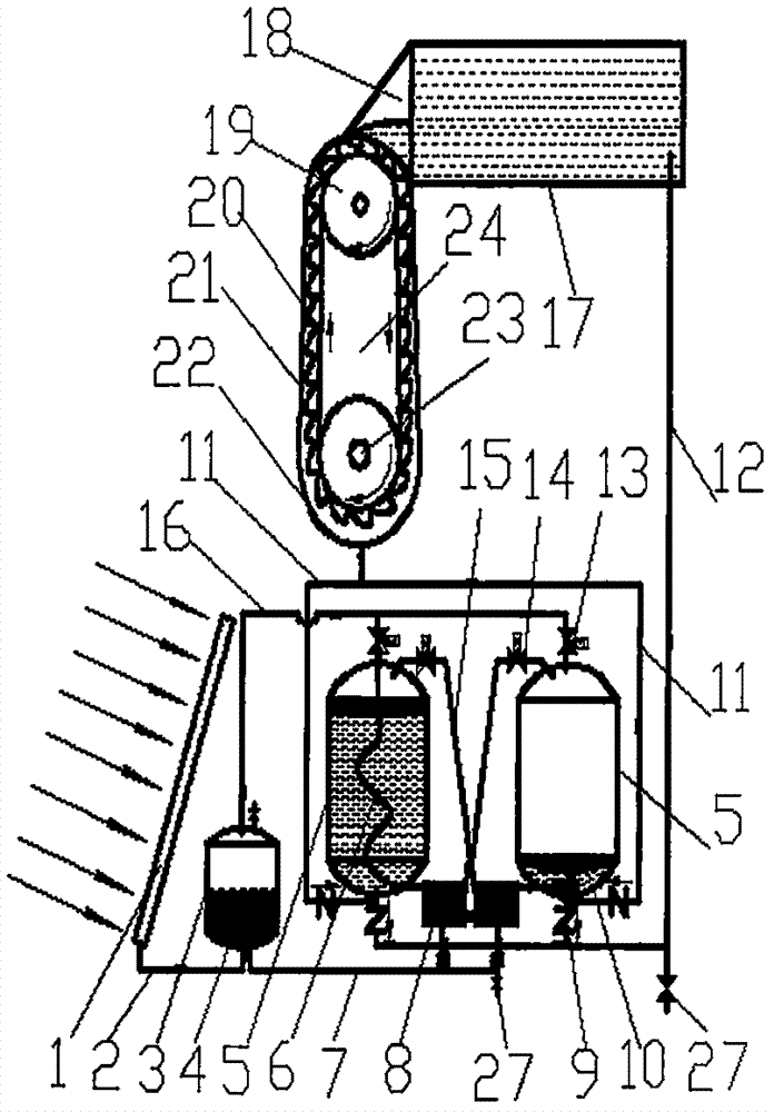
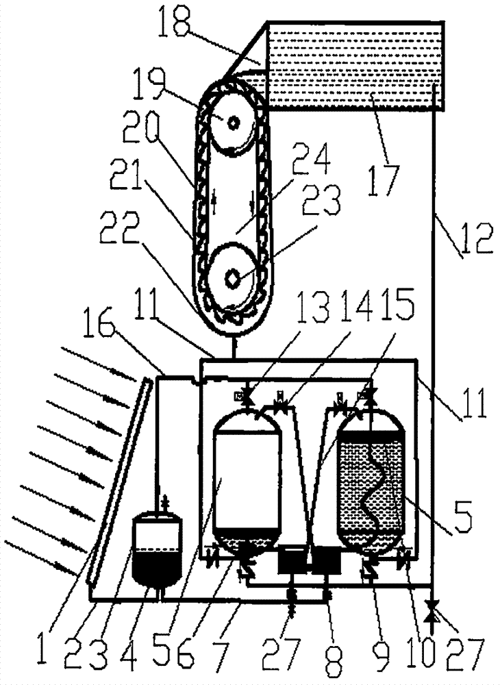
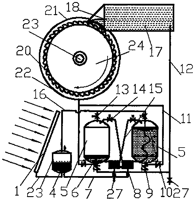
[0030] like figure 1 , figure 2 , image 3 , Figure 4 , Figure 11 The shown a kind of thermal energy water extraction and energy storage power generation equipment includes a solar vacuum tube heat collector 1, a steam boiler 3, a generator, and a grid-connected terminal device. The vacuum tube heat collector 1 communicates with a heat pipe 2 and a boiler 3 The heat exchanger 4 inside and the hot steam pressure pipe 16 of the boiler 3 are connected to the first pressurized water tank 5 filled with water. Below the water outlet of the electronically controlled water valve 18, a gravity-rotating water wheel 24 composed of a plurality of water receiving buckets 20 is set. Tank 5, the second pressurized water tank 5 enters the return water to generate pressure and presses the hot steam into the water tank formed by the condensing and returning surface cold coil 8, and the steam condenses and leaves heat to another water tank formed by the surface cooling coil 8 to the boile...
PUM
 Abstract
Description
Claims
Application Information