A Multistage Axial Flow Compressor with Self-Adaptive Blowing and Suction of Front and Rear Stage Stators

An axial flow compressor, self-adaptive technology, applied in the direction of mechanical equipment, machine/engine, liquid fuel engine, etc., can solve the problems of non-adaptive, limited range of working conditions, difficult engineering realization, etc., to achieve broad and effective work The range of operating conditions, the limited range of avoiding operating conditions, and the effect of avoiding stall

Active Publication Date: 2020-10-23
BEIHANG UNIV
View PDF5 Cites 0 Cited by
  • Summary
  • Abstract
  • Description
  • Claims
  • Application Information

AI Technical Summary

Problems solved by technology

[0004] After decades of research, many scientific researchers have gained a deep understanding of the flow mechanism in the three-dimensional corner area of ​​the compressor. However, due to the complexity of its flow structure, as well as the limitations and reliability of experimental measurements and numerical simulations, At present, the accurate prediction and reliable control of the three-dimensional corner separation flow of the compressor have not been well realized according to the existing mechanical research results; the research on the three-dimensional corner separation flow mechanism, flow prediction and flow control of the compressor is always a high-performance Key Issues Concerned in Compressor Design
[0005] At present, the flow control technology for the separation and stall of the compressor vane angle area can be divided into two categories: active control technology and passive control technology in terms of whether additional energy is introduced: active control technology mainly includes plasma excitation, boundary layer Blowing suction technology, synthetic jet, etc.; passive control technology mainly includes vortex generator, wing knife, end wall shape, etc.; boundary layer suction technology in active control technology has the characteristics of wide adaptability and obvious benefits, but it needs to introduce additional energy , is not easy to realize in engineering; the existing traditional passive control technology is not self-adaptive, and the range of effective working conditions is often limited, which fails to solve the problem of corner separation of the next generation of high-load compressors in engineering

Method used


Image

  • A Multistage Axial Flow Compressor with Self-Adaptive Blowing and Suction of Front and Rear Stage Stators
  • A Multistage Axial Flow Compressor with Self-Adaptive Blowing and Suction of Front and Rear Stage Stators
  • A Multistage Axial Flow Compressor with Self-Adaptive Blowing and Suction of Front and Rear Stage Stators

Examples


Embodiment 1

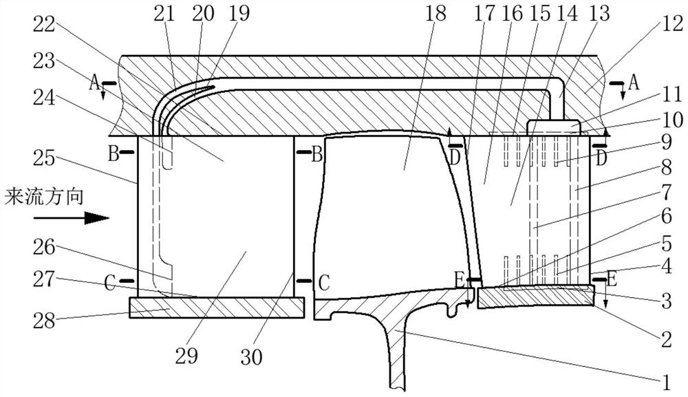
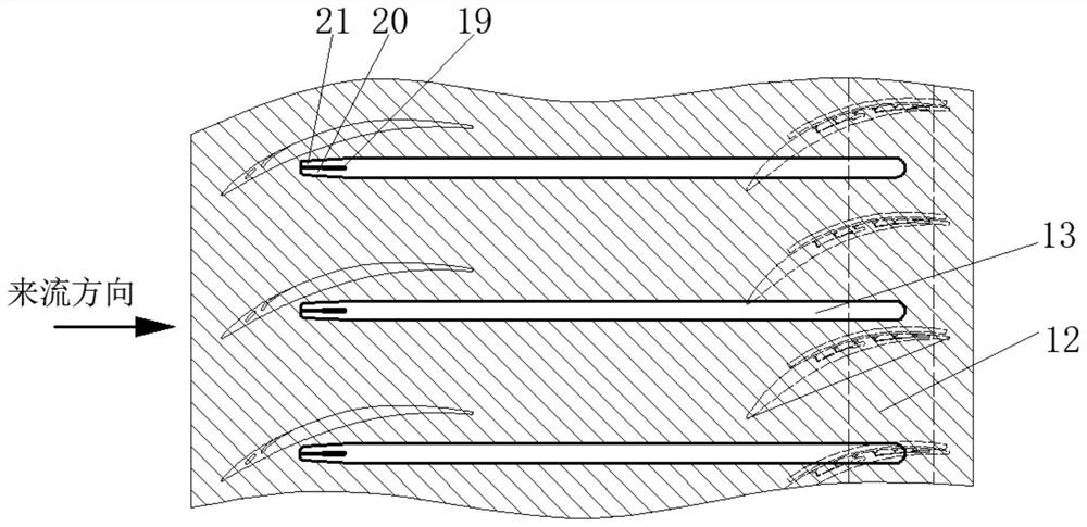
[0026] like figure 1 As shown, the multi-stage axial flow compressor of the present invention includes the front stage stator blade 23, the rotor blade 18, the rear stage stator blade 16, the casing 12 and the air induction pipe 13, 20, 21 structure located inside the casing 12; One side of the stage stator blade 23 is connected to the casing 12 and has a casing side end wall 22, and the other side is connected to the hub 28 and has a hub side end wall 27; the rotor blade 18 is located downstream of the front stage stator blade 23 and passes through the rotor wheel The disk 1 is connected to the engine shaft, and there is a blade tip gap between the rotor blade 18 and the casing 12; the rear stage stator blade 16 is located downstream of the rotor blade 18, and one side of the stator blade 16 is seamlessly connected with the casing 12, and has a casing side end wall 15, the other side is connected with the hub 2 and has a hub-side end wall 6.

[0027] On the side of the sucti...

Embodiment 2

[0032] This embodiment is basically the same as Embodiment 1, except that there are multiple rotor-stator stages between the front stage stator and the rear stage stator.


PUM


Abstract

The invention relates to a multistage axial flow compressor, and discloses a multistage axial flow compressor capable of achieving front-back stage stator self-adaptive air blowing and suction. The multistage axial flow compressor comprises a front stage stator blade, a rotor blade, a rear stage stator blade, a receiver and an air guide pipe structure located inside. The front stage stator blade is fixed to the upstream of the receiver and provided with a jet flow groove structure. The rotor blade is located between the front stage stator blade and the rear stage stator blade. The rear stage stator blade is provided with a suction groove structure which communicates with the jet flow groove of the front stage stator blade through the air guide pipe located inside the receiver. According to the characteristic stage-by-stage pressurization of the multistage compressor, under the pressure difference effect of front and back stage stator blade channels, self-adaptive suction and jet flow are formed, separated flow of a three-dimensional angle area of the stator end area of the multistage compressor is effectively suppressed, speed loss is prevented from occurring too early, the effective working station range of the compressor is widened, the blade channel flow ability of the multistage compressor is improved, and separation of the three-dimensional angle area of the stator blade and the loss caused by separation are reduced.

Description

technical field [0001] The invention relates to the field of multi-stage axial flow compressors, in particular to a multi-stage axial flow compressor with self-adaptive blowing and suction of front and rear stage stators. Background technique [0002] The compressor is the core component of the aviation gas turbine engine. It is composed of multi-stage rotors and stators arranged in a staggered order, and its function is to increase the gas pressure rise. [0003] In the flow inside the compressor, the secondary flow in the blade and end wall corner area caused by the large reverse pressure gradient is an inherent and complex flow phenomenon, so the loss is the main source of loss in the flow inside the compressor; three-dimensional The flow congestion caused by corner separation / stall makes the performance of the compressor drop sharply, which has a crucial impact on the pressure ratio, efficiency, margin and other performance of the compressor; the development of modern ae...

Claims


Application Information

Patent Timeline
Patent Type & Authority Patents(China)
IPC IPC(8): F04D29/54F04D27/00
CPCF04D27/00F04D29/54F05D2240/12
Inventor 柳阳威唐雨萌陆利蓬王鸣
Owner BEIHANG UNIV
Why Eureka
Try Eureka