Eureka AIR delivers breakthrough ideas for toughest innovation challenges, trusted by R&D personnel around the world.

Battery pack structure

A technology of battery packs and batteries, applied in structural parts, battery pack parts, circuits, etc., can solve problems such as imperfect overcurrent protection measures, current damage to batteries or products, and failure to meet the requirements of use, so as to prevent collisions and bursting, Reduced manufacturing cost and improved safety

Pending Publication Date: 2017-09-22
HUIZHOU BLUEWAY ELECTRONICS
View PDF7 Cites 2 Cited by
  • Summary
  • Abstract
  • Description
  • Claims
  • Application Information

AI Technical Summary

Problems solved by technology

[0002] At present, electric tools and electronic products are widely used in many fields. Electric tools and electronic products generally need battery power supply. However, because the voltage of a single battery is relatively low, it generally cannot meet the requirements of use. Use batteries in series or in parallel
In the prior art, the method of connecting multiple batteries in series and in parallel is relatively simple, and there are the following problems in the use process: 1. The safety performance is low, and the existing overcurrent protection measures are not perfect, and the battery is often damaged by excessive current or The product itself
2. It is bulky. General terminal equipment tends to be small and flexible. If the packaging volume of the battery is too large, it will have a certain impact on the product
3. It is easy to be damaged. If the existing battery pack collides, it is easy to cause damage to the battery

Method used


Image

  • Battery pack structure
  • Battery pack structure
  • Battery pack structure

Examples


Embodiment 1

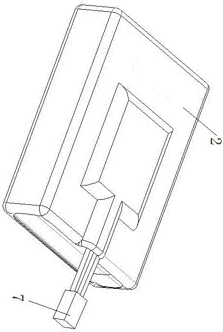
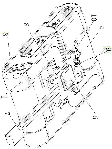
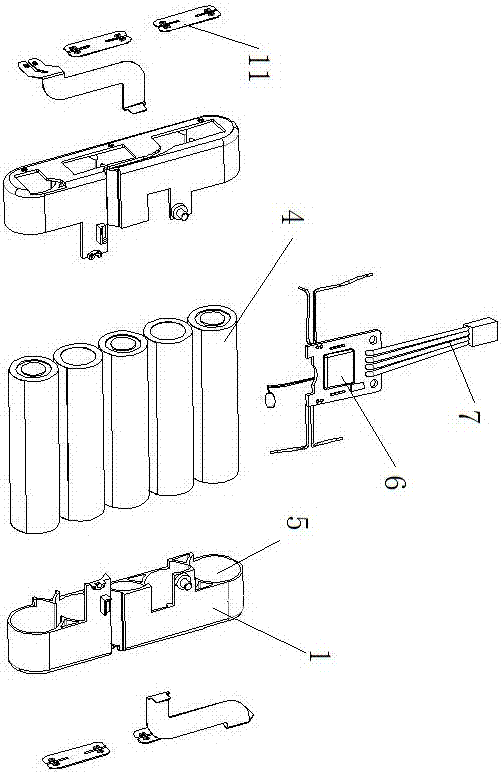
[0022] As shown in the accompanying drawings, the battery pack structure includes a bracket 1, a protective cover 2 and a buffer 3, the buffer is arranged around the bracket, and the protective cover is wrapped around the bracket and the buffer; the bracket is provided with a battery 4, installed Groove 5, protective plate 6 and connector 7, battery is placed in the installation groove, and battery can be by multi-section, and multi-section battery is connected by wire or metal sheet, present embodiment adopts nickel sheet 11 to connect all batteries together, connect The plug-in is connected to the protection board, and the battery pack of the connector outputs electric energy and signals; an over-current protector 8 and a temperature sensor 9 are arranged on the protection board, and both the over-current protector and the temperature sensor are connected to the positive pole or the negative pole of the battery.

[0023] Specifically, the overcurrent protector is a rectangula...

Embodiment 2

[0029] The color of the heat-shrinkable sleeve of the battery pack structure in the second embodiment is black, and the size of the rectangular copper foil is: 1.50mm in length and 0.75mm in width. At this time, the protection current of the overcurrent protector is greater than or equal to 15A, and the other Components and connection methods are the same as those in Embodiment 1. Because the battery pack needs to be coded during the production process, and the black battery pack code is relatively easier to identify.


PUM

PropertyMeasurementUnit
currentaaaaaaaaaa

Abstract

The invention relates to a battery pack structure. The battery pack structure comprises a support (1), a protection sleeve (2) and buffers (3), wherein the buffers are arranged around the support, the protection sleeve wraps the support and the buffers, a battery (4), an installation groove (5), a protection plate (6) and a connector (7) are arranged on the support, the battery is placed in the installation groove, the connector is connected with the protection plate, and an overcurrent protector (8) and a temperature sensor (9) are arranged on the protection plate and both are connected with a positive electrode or a negative electrode of the battery. By the battery pack structure, the safety of a battery pack can be ensured, and an overcurrent phenomenon is prevented; moreover, compared with other battery packs with same capacity, the battery pack structure has the advantage of small size and is convenient to use; and meanwhile, the performance the battery pack is enabled not to be damaged during collision.

Description

technical field [0001] The invention relates to the field of battery pack manufacturing, in particular to a battery pack structure. Background technique [0002] At present, electric tools and electronic products are widely used in many fields. Electric tools and electronic products generally need battery power supply. However, because the voltage of a single battery is relatively low, it generally cannot meet the requirements of use. Batteries are used in series or in parallel. In the prior art, the method of connecting multiple batteries in series and in parallel is relatively simple, and there are the following problems in the process of use: 1. The safety performance is low, and the existing overcurrent protection measures are not perfect, and excessive current often damages the battery or The product itself. 2. It is bulky. General terminal equipment tends to be compact and flexible. If the packaging volume of the battery is too large, it will have a certain impact on...

Claims


Application Information

Patent Timeline
Patent Type & Authority Applications(China)
IPC IPC(8): H01M2/10H01M2/20H01M2/34
CPCH01M50/20H01M50/502H01M50/572Y02E60/10
Inventor 周玲林宗溪李润朝朱立湘尹志明林军
Owner HUIZHOU BLUEWAY ELECTRONICS
Why Eureka
Eureka Blog
Learn More