
Coaxial filter with frame structure

A frame structure and filter technology, which can be applied to waveguide-type devices, circuits, connecting devices, etc., and can solve the problems of large structure and height.

Active Publication Date: 2020-03-06
TELEFON AB LM ERICSSON (PUBL)
View PDF9 Cites 0 Cited by
  • Summary
  • Abstract
  • Description
  • Claims
  • Application Information

AI Technical Summary

Problems solved by technology

However, such a filter has the disadvantage that the overall volume, especially the height, is relatively large

Method used


Image

  • Coaxial filter with frame structure
  • Coaxial filter with frame structure
  • Coaxial filter with frame structure

Examples


Embodiment Construction

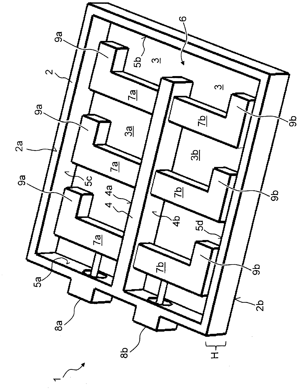
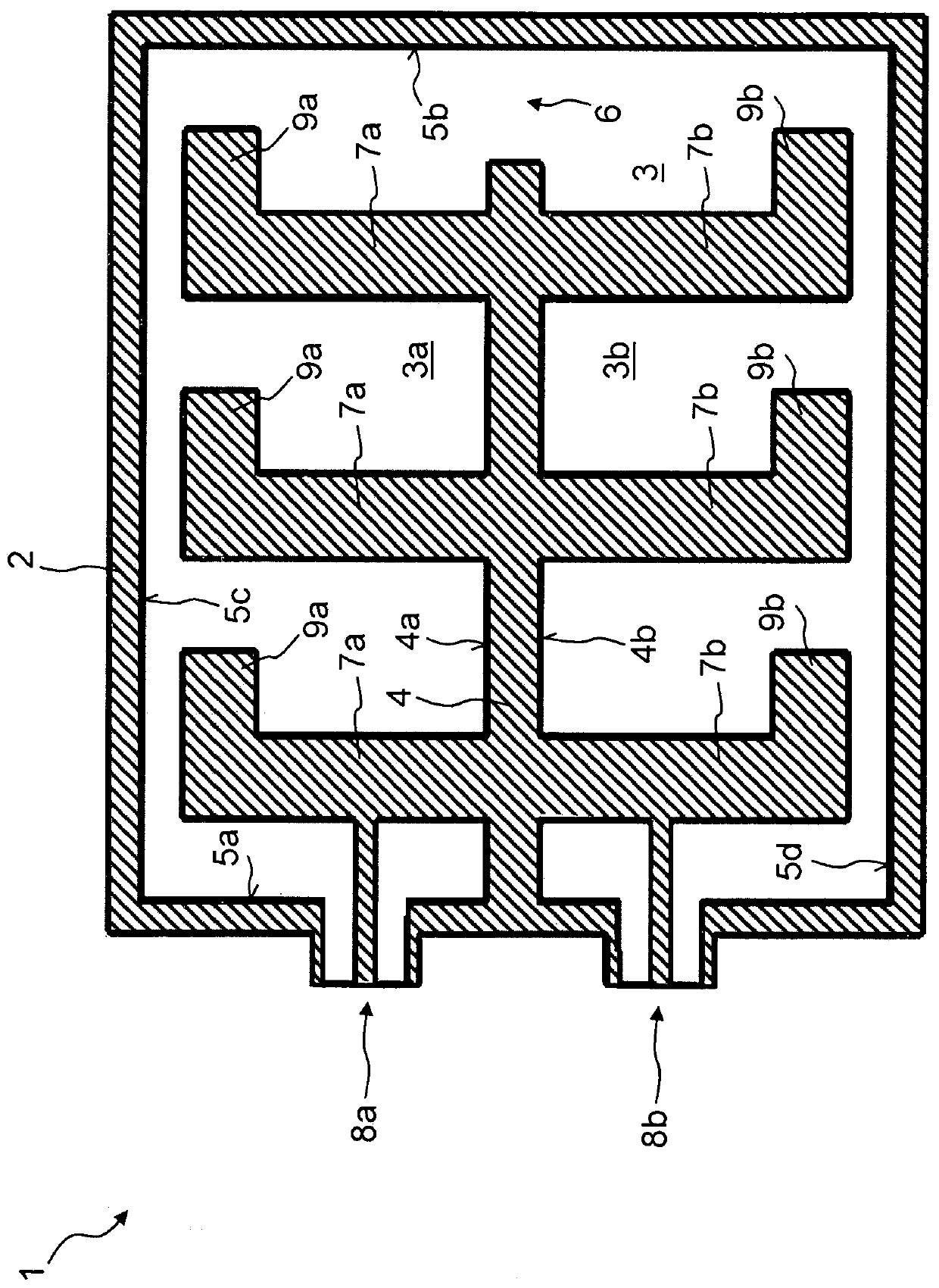
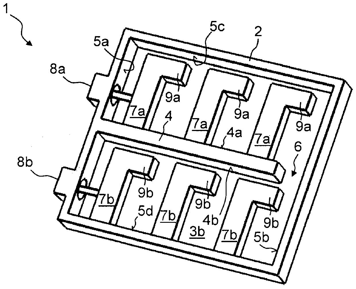
[0019] Figure 1A A spatial illustration of the coaxial filter 1 according to the invention in frame construction is shown, with the cover device removed. Figure 1B show Figure 1A A sectional view of the coaxial filter 1 according to the invention in the longitudinal direction extending parallel to the removed cover arrangement. The main component of the coaxial filter 1 is at least one filter frame 2, which is made of an electrically conductive material and has an accommodating space 3, wherein the accommodating space 3 is arranged on the at least one electrically conductive Inside the filter frame 2 , the at least one electrically conductive filter frame 2 thus forms the edge of the receiving space 3 . The filter frame 2 is preferably rectangular or square in plan view or at least approximates this shape.

[0020] A cover device (not shown) closes the open end, that is to say the opposite wide sides of the at least one filter frame 2 . exist Figure 1A , the cover dev...


PUM


Abstract

The present invention relates to a coaxial filter (1) of a frame construction mode having at least one filter frame (2) made of a conductive medium and a holding space (3). The cover device encloses the containing space from all sides (3). At least one first internal resonance conductor (7a) is disposed in the accommodating space (3). The at least one first internal resonance conductor (7a) is electrically connected to one side of the at least one conductive filter frame (2) and extends from that side towards the other side of the conductive filter frame (2), in particular the opposing side, and spaced open distance in front of the opposed side of the conductive filter frame (2) and / or the opposed side of the conductive filter frame (2).

Description

technical field [0001] The invention relates to a coaxial filter with frame structure. Background technique [0002] Filters in communication technology and high-frequency technology are always used when only certain frequency parts of the signal are to be further processed. In addition to high-pass filters or low-pass filters there are band-pass filters or band-stop filters. Filters can not only be realized digitally, but can also be constructed with the aid of discrete structural elements. In this case, the filter is embodied on a printed circuit board or as a coaxial filter in the form of a milled or cast cavity structure. Filters of coaxial design are generally produced by die-casting, wherein fine adjustment can be performed by means of additional screw-in tuning elements. [0003] Such a filter is known, for example, from DE 10 2004 010 683 B3. However, such a filter has the disadvantage that the overall volume, in particular the height, is relatively large. This ...

Claims


Application Information

Patent Timeline
Patent Type & Authority Patents(China)
IPC IPC(8): H01P1/202
CPCH01P1/202H01P1/205H01P1/2053H01P5/02
Inventor F·罗特莫泽J·尼塔
Owner TELEFON AB LM ERICSSON (PUBL)
Learn More